Double-frequency broadband E-shaped microstrip antenna

A microstrip antenna and broadband technology, which is applied to antennas, slot antennas, and devices that make antennas work in different frequency bands at the same time, can solve the problem that dual-band broadband high-gain antennas cannot meet requirements, frequency band control is difficult, and communication quality is affected. and other problems, to achieve the effect of uniform current distribution, easy circuit integration, and improved communication quality.

Inactive Publication Date: 2009-09-09
HARBIN ENG UNIV
View PDF0 Cites 21 Cited by
  • Summary
  • Abstract
  • Description
  • Claims
  • Application Information

AI Technical Summary

Problems solved by technology

[0002] At present, the antennas for the same purpose have the following disadvantages: (1) At present, the gain of the antenna is required to be relatively high, such as a gain of 4-6dBi
In practical applications, almost all the radio wave radiation in the upward direction is wasted, so the gain is relatively low, and the frequency band is relatively narrow. Antennas with such gain waste signals in vain, thus affecting communication quality.
(2) Most of the currently used indoor coverage and wireless LAN antennas are ceiling-mounted antennas, whose frequency band control is difficult, and users hope to use dual-band broadband antennas, which means making full use of resources and improving the flexibility of antennas
Current indoor coverage and WLAN antennas cannot meet this demand
(4) The current communication has higher and higher bandwidth requirements, and the current ceiling-mounted antennas and indoor antennas cannot meet the current communication needs, especially the dual-band broadband high-gain antennas cannot meet the requirements

Method used


Image

  • Double-frequency broadband E-shaped microstrip antenna
  • Double-frequency broadband E-shaped microstrip antenna
  • Double-frequency broadband E-shaped microstrip antenna

Examples


Embodiment 1

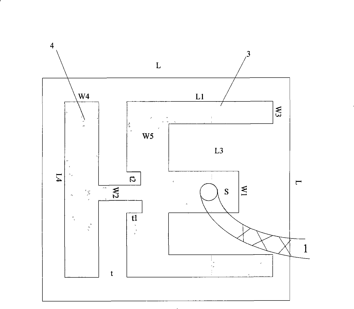
[0031] Such as figure 1 , 2 As shown in and 3, the 50Ω main feeder 1 is directly connected to the feeding SMA connector 2 of the microstrip antenna, passes through the ground plane and the dielectric plate through the SMA connector, and directly contacts the E-shaped patch. Adjust L 3 , t 1 and t 2 The working frequency and working bandwidth of the high-frequency band can be determined, and the designed antenna works at 5.1GHz to 5.8GHz to meet the communication needs of wireless local area networks and the like.

[0032] Adjust W 4 The size of the antenna can change the working frequency of the designed antenna in the low frequency band, when W 4 When it is narrow, the antenna resonates below 2.4GHz at the low end. When increasing W 4 width, the resonance point at the low end of the antenna will move to the high frequency band. L 4 is the length of the T-shaped patch, W 2 is the width of the feed arm of the T-shaped patch, the gap t is the distance between the E-shap...

Embodiment 2

[0036] Such as Figure 15As shown, according to the relationship between antenna size and frequency (wavelength), the size of the E-shaped antenna and the size of the T-shaped antenna are appropriately changed. This antenna can be used in mobile communications of GSM, WCDMA, CDMA2000 and TD-SCDMA. The specific design dimensions are as Figure 15 shown. Figure 15 L in = 120mm; W 3 =36mm,L 1 =58mm;W 1 =18mm;L 3 = 5 mm; t ≈ 4 mm. Among them, the parameters of the curved T-shaped patch can be determined as a symmetrical dipole antenna. The two non-connecting ends of the T-shaped patch are bent to realize miniaturization.

Embodiment 3

[0038] Such as figure 1 and Figure 15 As shown in , the proposed dual-band broadband E-shaped antenna and T-shaped antenna can also be used as a broadband omnidirectional antenna.


PUM


Abstract

The invention provides a double-frequency broadband E-shaped microstrip antenna, comprising an E-shaped patch 3. A main feeder line 1 is directly connected to an SMA joint 2 of coaxial feeding point of the E-shaped patch 3, the SMA joint passes through the ground and medium and then is directly in contact with the intermediate arm of the E-shaped patch 3, another two arms of the E-shaped patch 3 are symmetrically distributed at the two sides of the feeding point and have a distance of L3 from the edge of the intermediate arm, the E-shaped patch 3 is connected with a T-shaped patch (bent T-shaped patch) 4 by loading to form a main radiating unit of the antenna, a width t is arranged between the E-shaped patch 3 and T-shaped patch (bent T-shaped patch), and a slot with width t2 and depth t1 is respectively arranged at the two sides of the joint between the T-shaped patch (bent T-shaped patch) and the E-shaped patch. The invention has relatively high gain, wide working frequency band, uniform current distribution, light weight and small volume, can effectively improve communication quality, is easily integrated with a circuit, and can be widely used for a portable device and in indoor coverage and wireless local area network.

Description

(1) Technical field [0001] The invention relates to a dual-frequency E-shaped microstrip antenna. Specifically, it is a microstrip antenna used for low and medium gain indoor coverage and wireless local area network in mobile communication systems, and the working frequency band is 2400-2500 and 5100-5850MHz. (2) Background technology [0002] At present, antennas for the same purpose have the following disadvantages: (1) At present, the gain of the antenna is required to be relatively high, for example, a gain of 4-6 dBi is required. However, the existing indoor antennas and wireless LAN antennas are mostly in the form of traditional monopoles and symmetrical arrays, so the direction diagrams are equal up and down. In practical applications, almost all upward radio wave radiation is wasted, so the gain is relatively low and the frequency band is relatively narrow. Antennas with such gain waste signals in vain, thereby affecting communication quality. (2) Most of the curre...

Claims


Application Information

Patent Timeline
Patent Type & Authority Applications(China)
IPC IPC(8): H01Q13/08H01Q13/10H01Q5/01H01Q5/10
Inventor 杨晓冬李迎松刘乘源
Owner HARBIN ENG UNIV
Why Eureka
Try Eureka