Staggered driving PWM compensating current generator and control method thereof

A compensation current and generator technology, applied in reactive power compensation, AC network to reduce harmonics/ripples, reactive power adjustment/elimination/compensation, etc., can solve the problem of increasing the switching loss of semiconductor power devices and increasing the volume of inductors , weight and cost, compensation current generator technical performance limitations and other issues, to achieve the required effects of reducing loss, reducing switching loss, and reducing switching speed

Inactive Publication Date: 2009-09-09
山东华天科技集团股份有限公司
View PDF0 Cites 13 Cited by
  • Summary
  • Abstract
  • Description
  • Claims
  • Application Information

AI Technical Summary

Problems solved by technology

However, increasing the inductance of the output inductor will limit the maximum change rate of the output current, affect the speed and effect of tracking compensation, and increase the volume, weight and cost of the inductor; while increasing the carrier frequency will increase the switching loss of semiconductor power devices, reducing efficiency, and is limited by the switching speed of semiconductor power devices, it is impossible to increase excessively
A trade-off between several limiting factors is therefore required, resulting in limitations on the technical performance of the compensation current generator
[0006] 2) When the compensation current generator is working, there is also a large ripple current in the DC circuit of its inverter bridge, which causes the DC bus voltage to fluctuate and produces a large loss in the DC bus capacitor
In order to ensure the normal operation of the device, a large DC bus capacitor is required, which increases the volume, weight and cost of the device

Method used


Image

  • Staggered driving PWM compensating current generator and control method thereof
  • Staggered driving PWM compensating current generator and control method thereof
  • Staggered driving PWM compensating current generator and control method thereof

Examples


Embodiment Construction

[0033] The present invention will be further described below in conjunction with the accompanying drawings and embodiments.

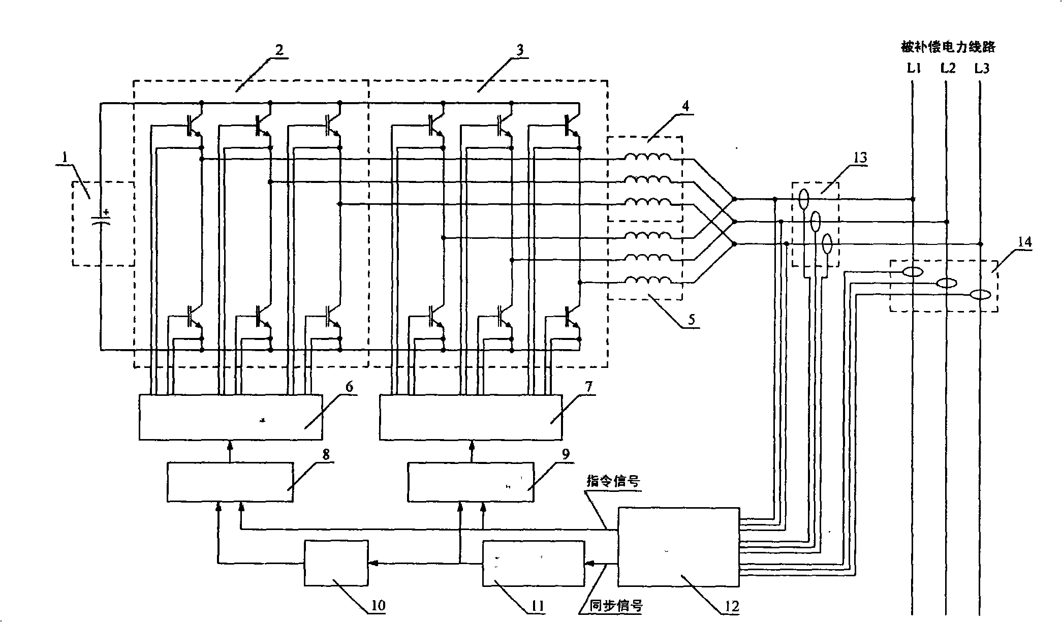
[0034] figure 1 It is the first embodiment in which the interleaved drive PWM compensation current generator is used in a three-phase three-wire power line. According to the purpose of compensation, it can be used as active power filter or static synchronous compensator to compensate harmonic current and reactive current in power line.

[0035] like figure 1As shown, an interleaved drive PWM compensation current generator, which consists of DC bus capacitor 1, inverter bridge I 2, inverter bridge II 3, inductor I 4, inductor II 5, drive circuit I 6, drive circuit II 7. PWM pulse width modulator I 8, PWM pulse width modulator II 9, inverter 10, triangular wave generator 11, operation and control unit 12, current transformer group I 13, and current transformer group II 14; wherein , the DC buses of the inverter bridge I 2 and the inverter bridge II 3 a...


PUM


Abstract

The invention discloses a staggered driving PWM compensating current generator and a control method thereof. Two inversion bridges are connected in parallel to operate and respectively output compensating current through an inductor, effective components of the compensating current, which correspond to command signals are same, the two inversion bridges are overlapped after being connected in parallel and output twice the total current of the signal inversion bridge, carrier frequency ripple current components generated by PWM modulation in the compensating current output by the two inversion bridges through the inductor are approximately reverse in a constant amplitude and can be mutually cancelled out, thus the ripple component in total output current is obviously reduced. The staggered driving PWM compensating current generator can use the lower carrier frequency and the smaller output inductor to obtain the output ripple current which is obviously reduced compared with the output ripple current in the prior technical method; in addition, the effective value of the ripple current in a DC loop is reduced to about 46 percent of the effective value of the ripple current in the prior technical method, thus the indexes including the current tracking speed, the output ripple current, the wastage, the efficiency, the cost, and the like of the PWM compensating current generator can be synthetically improved.

Description

technical field [0001] The invention relates to a PWM compensation current generator, in particular to an interleaved driving PWM compensation current generator and a control method thereof for actively tracking and compensating harmonic currents and reactive currents in a power system. Background technique [0002] The active compensation of harmonic current and reactive current in the power system by modern power electronic technology is an important content in the flexible power transmission technology (FACTS) and consumer power technology (D-FACTS) developed in recent years. For example, active power filter (APF) and static synchronous compensator (STATCOM), etc., belong to the compensation current generator manufactured by modern power electronic technology. [0003] In order to achieve high-efficiency and high-speed effects, this type of compensation current generator usually uses a pulse width modulation (PWM) method to generate the required fast-changing high-intensi...

Claims


Application Information

Patent Timeline
Patent Type & Authority Applications(China)
IPC IPC(8): H02J3/01H02J3/18H03K7/00
CPCY02E40/30Y02E40/40
Inventor 李建明王德涛李波
Owner 山东华天科技集团股份有限公司
Why Eureka
Try Eureka