
Pantograph type current collector of electric automobile and automatic rapid charging station

An electric vehicle, fast charging technology, applied in the direction of electric vehicle charging technology, electric vehicles, charging stations, etc., can solve the problems of failure to meet reliable practical requirements, high manufacturing costs, and inability to use charging stations to start vehicles

Inactive Publication Date: 2009-09-16
田耕
View PDF3 Cites 58 Cited by
  • Summary
  • Abstract
  • Description
  • Claims
  • Application Information

AI Technical Summary

Problems solved by technology

In the description of the third patent, the problems existing in the first two patents are described, but in ZL200710094281.1, there are still the following defects that cannot meet the reliable practical requirements in principle:
[0005] 1. The vertical action of the multi-stage cylinder supporting the power receiving plate is analyzed in principle to have low action accuracy, because there is no aeroelastic lever amplification link, which makes the elastic working range insufficient and the contact pressure difficult to guarantee
[0006] 2. There is a pin shaft that acts as a swing support, which can make the two receiving plates of the electric vehicle contact with the double contact wires at the output end of the charging station at the same time, but it cannot guarantee the large-area contact between the receiving boards and the double contact wires at the output end of the charging station. planar contact
[0007] 3. Electricity is received in a static state, and the vertical jacking form is not conducive to charging the vehicle during driving. The static state receives electricity and wastes the charging time of low-speed driving, opening and closing the door, and starting the vehicle before parking, and the electric energy of the charging station cannot be used to start the vehicle.
[0008] 4. There are many special precision parts, high manufacturing cost and low reliability

Method used


Image

  • Pantograph type current collector of electric automobile and automatic rapid charging station
  • Pantograph type current collector of electric automobile and automatic rapid charging station
  • Pantograph type current collector of electric automobile and automatic rapid charging station

Examples


Embodiment Construction

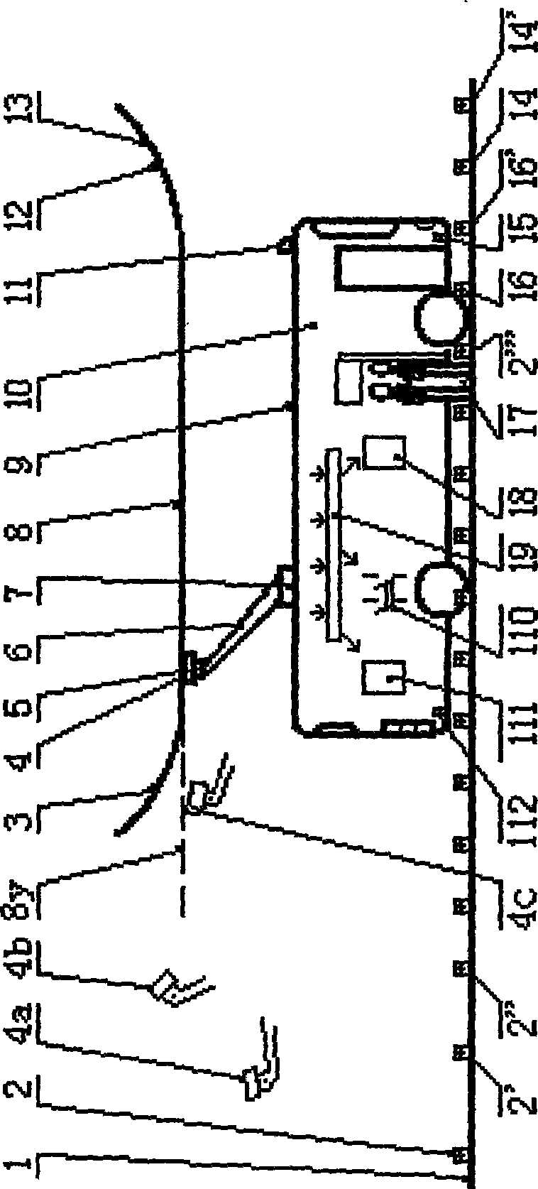
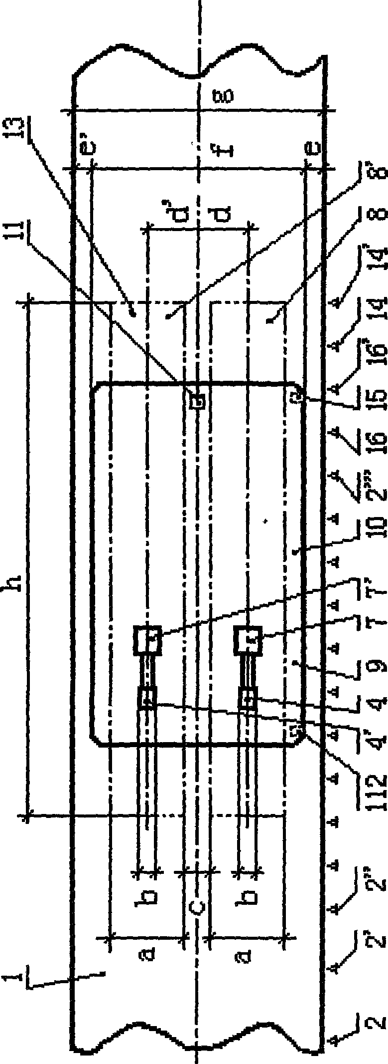
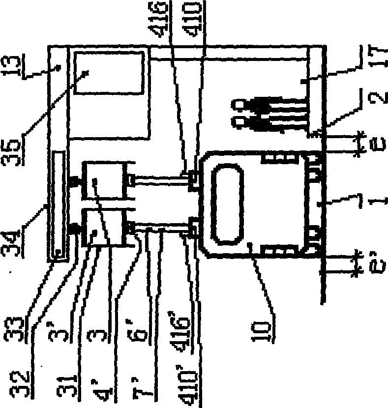
[0049] [1], figure 1 Is: A schematic right side view of a pantograph and an automatic fast charging station for an electric vehicle. figure 1 Including: lane 1, bow signal point 2, contact plate introduction arc 3, electric slider 4, universal head 5, bow arm 6, pantograph assembly 7, contact plate 8, roof 9, electric vehicle 10. Camera 11, contact plate lead-out arc 12, electric vehicle charging station 13, power-off bow down signal point 14, signal receiver 15, charging signal point 16, bus station 17, acoustic signaler 18, controller 19, contact Device 110, gas circuit switch 111, signal receiver 112, point 2', 2", 2"' after the bow-up signal, point 16' after the charging signal, point 14' after the bow-down signal after power-off; bow down, receiving power The lowest position of the slider 4 is represented as 4a; the bow is raised to adjust the highest position of the receiving slider 4, and its position is represented as 4b; the bow is charged, and the receiving slider 4...


PUM


Abstract

The invention provides a pantograph type current collector of electric automobile and an automatic rapid charging station. Two pantograph type current collectors are parallel installed on the electric automobile top which has a single main shaft driven by gas cylinder or hydraulic pressure cylinder, and can act local arc movement, a gimbal is installed on the current collector end, a current slide block is fixed on the gimbal; an output end of the electric automobile charging station is two parallel contact plates on the automobile road upper part, two ends of the contact plate has introduce arc and educe arc; the electric automobile runs over the automobile charging station with standard speed along the road under control by relative sensing, detecting and controller which can complete whole process of collecting bow, charging, de-charging and depressing bow automatically.

Description

(1) Technical field: [0001] The invention relates to charging of an electric vehicle, in particular to a pantograph and an automatic fast charging station of the electric vehicle. (two) background technology: [0002] Supercapacitor electric vehicles and electric vehicles with supercapacitor and battery composite power supply can be used for urban buses and other short-distance transportation. Electric vehicles will play an important role in energy saving and emission reduction and improving the livable quality of big cities. Charging is One of the key links in electric vehicle technology. [0003] The characteristics of supercapacitor charging are: large charging current, short charging time, short continuous driving distance after charging, short recharging interval, and frequent charging. Therefore, it is required that the contact area between the output end of the charging station and the receiving end of the electric vehicle should be large and have reasonable contact ...

Claims


Application Information

Patent Timeline
IPC IPC(8): B60L5/18B60L5/20B60L5/04B60M1/00
CPCB60L5/16B60L5/42B60L53/11B60L53/14B60L53/32B60L53/36B60L2200/18B60M1/36Y02T10/70Y02T10/7072Y02T90/12Y02T90/14
Inventor 田耕
Owner 田耕
Learn More