System for rapidly pyrolysing and liquefying biomass

A liquefaction system and biomass technology, applied in the field of biomass rapid pyrolysis liquefaction system, can solve the problems of increasing system complexity and manufacturing cost, increasing process difficulty and cost, reducing biomass conversion rate, etc., to achieve product improvement value, avoiding equipment investment, and reducing operating costs

Inactive Publication Date: 2009-09-16
GUANGZHOU DEVOTION THERMAL TECH
View PDF1 Cites 20 Cited by
  • Summary
  • Abstract
  • Description
  • Claims
  • Application Information

AI Technical Summary

Problems solved by technology

But, as can be seen from the above description, the No. CN200510057215.8 patent has the following disadvantages: first, the system needs to be equipped with a special nitrogen supply system to supply nitrogen to the pyrolysis reaction tower and heat carrier heating tower, which Increased system complexity and manufacturing cost; second, the medium used to condense the pyrolysis gas in the condenser is water, therefore, the obtained bio-oil will contain a large amount of water, and special equipment is required to use it Further separation will increase the difficulty and cost of the process; thirdly, the non-condensable gas and carrier gas from the condenser are used as recovery gas, which is directly recycled as part of the fluidization gas and heat carrier heating of the pyrolysis reaction tower A part of the combustion gas in the tower, and a part of the circulating hot carrier gas in the feeding mechanism, therefore, on the one hand, the non-condensable gas that can be used as gas fuel does not form a gas product that can be transported to the outside, which leads to a loss of value. On the other hand, This mixed recovered gas contains a lot of water and tar, but it is directly used in the subsequent process without sufficient treatment, leading to a vicious cycle, which not only leads to a decrease in the conversion rate of biomass energy, but also causes equipment damage and even safety hazards. ACCIDENT

Method used


Image

  • System for rapidly pyrolysing and liquefying biomass

Examples


Embodiment 1

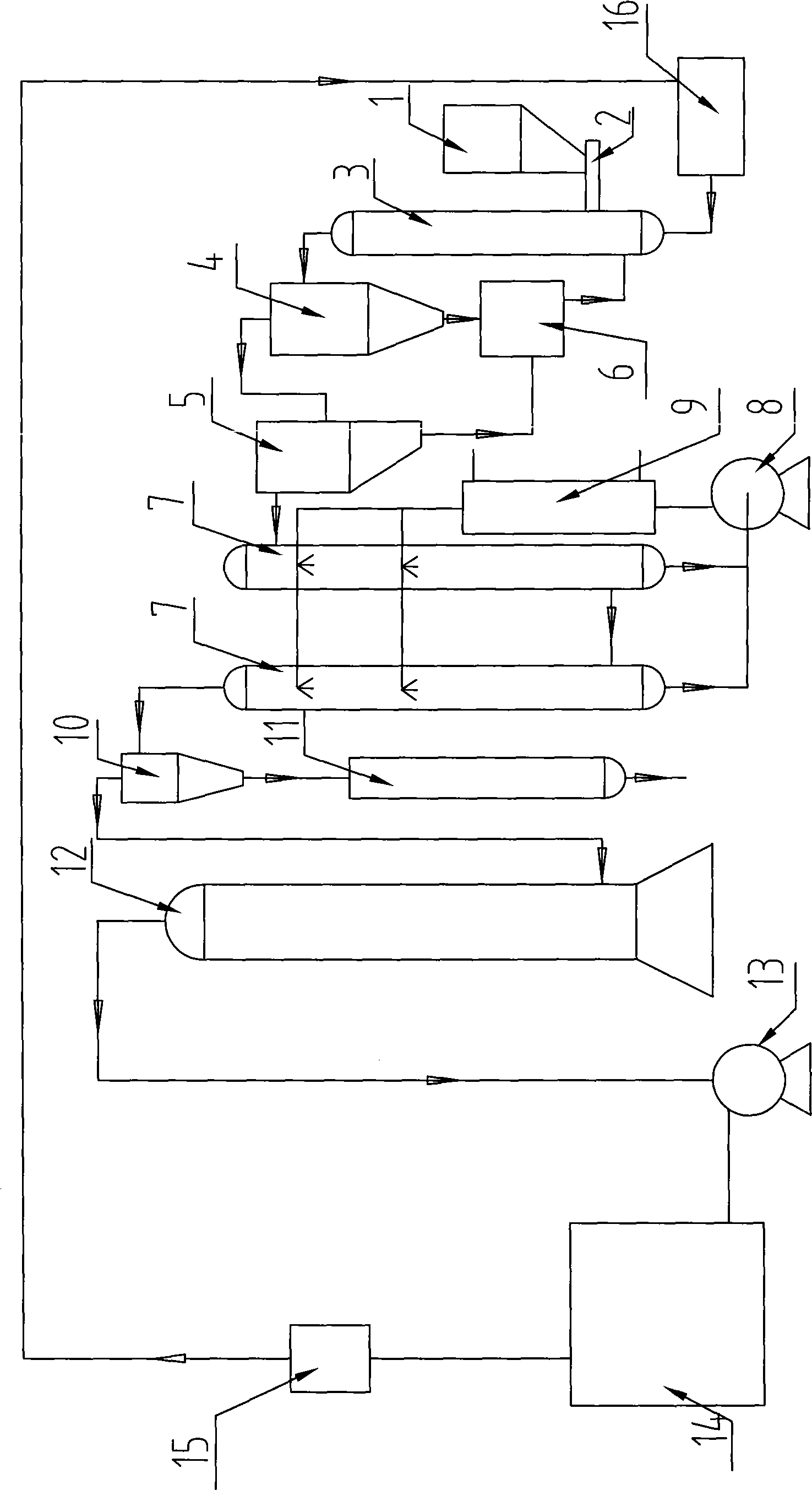
[0026] Please refer to figure 1 , the biomass rapid pyrolysis liquefaction system of the present invention comprises a pyrolysis reactor 3, a feeder connected to the biomass material inlet of the pyrolysis reactor 3 (comprising a storage bin 1 and a screw feeder 2 in this embodiment ), the reaction starter 16 connected to the thermal carrier gas inlet of the pyrolysis reactor 3, the gas-solid separation subsystem connected to the pyrolysis gas outlet of the pyrolysis reactor 3 (comprising a high-temperature cyclone separation device in this embodiment 4 and high-temperature gas-solid separation device 5), the bio-oil condensation reserve subsystem (comprising two condensing towers 7 in this embodiment, connected to the bio-oil outlet of the condensing tower 7) with the gas outlet of the gas-solid separation subsystem The oil storage tank 8, and the circulating bio-oil bypass) connected between the oil storage tank 8 and the condensing medium inlet of the condensation tower 7 a...

Embodiment 2

[0032] As another kind of scheme of the present invention, other parts are identical with embodiment 1, and difference is:

[0033] The biomass rapid pyrolysis liquefaction system of the present invention may also include a raw material pretreatment subsystem for pulverizing and drying biomass materials, a gas power generation sub-system for using the generated gas for a gas-fired generator set to generate electricity for the entire system, and An automatic operation monitoring subsystem used to control the orderly work of the entire system.

[0034] Only one condensing tower 7 may be provided and spray devices divided into three or more groups in the height direction of the condensing tower 7 may be used.

[0035] The thermal cycle medium heating and separation subsystem may include two independent thermal cycle medium heating devices and thermal cycle medium separation devices.


PUM


Abstract

The invention discloses a system for rapidly pyrolysing and liquefying biomass, which comprises a pyrolysis reactor, a feeding device connected with a biomass material inlet of the pyrolysis reactor, a reaction starter connected with a circulating heat supporting gas inlet, a gas-solid separation sub-system connected with a pyrolysis gas outlet of the pyrolysis reactor, a bio-oil condensing and reserving sub-system connected with a gas outlet of the gas-solid separation sub-system, and a thermal circulation medium heating and separating sub-system connected with a solid outlet of the gas-solid separation sub-system. The thermal circulation medium outlet of the thermal circulation medium heating and separating sub-system is connected with the thermal circulation medium inlet of the pyrolysis reactor, wherein the bio-oil condensing and reserving sub-system includes at least one heat exchanger that is applied for cooling partial obtained bio-oil to be used as a condensed medium of the bio-oil condensing and reserving sub-system. The system for rapidly pyrolysing and liquefying biomass can fully improve the utilization rate of biomass energy and reduce the operation cost thereof to the maximum degree.

Description

technical field [0001] The invention relates to a biomass energy conversion system, in particular to a biomass fast pyrolysis liquefaction system. Background technique [0002] With the continuous development of the world economy, energy and environmental issues have become increasingly prominent. The main energy sources currently used by human beings are oil, natural gas and coal. According to the statistics of the International Energy Agency, the lifespan of these three kinds of energy for human exploitation on the earth is only 40 years, 50 years and 240 years respectively. The development of new energy has become a major issue related to the sustainable development of human society. [0003] Biomass energy is the solar energy stored in plants by the photosynthesis of plants and solar energy. It is estimated that the annual energy stored in plants is equivalent to 10 times the world's main fuel consumption, while the utilization of energy as energy is less than 1% of t...

Claims


Application Information

Patent Timeline
Patent Type & Authority Applications(China)
IPC IPC(8): C10G1/00
Inventor 陈平常厚春李祖芹马革
Owner GUANGZHOU DEVOTION THERMAL TECH
Why Eureka
Try Eureka