Electric motor built-in false finger
A built-in, artificial finger technology, applied in the field of artificial fingers, can solve the problem of insufficient space for the artificial hand to effectively use, achieve the effect of anthropomorphizing the movement mode, improving the degree of integration, and reducing the volume
- Summary
- Abstract
- Description
- Claims
- Application Information
AI Technical Summary
Problems solved by technology
Method used
Image
Examples
specific Embodiment approach 1
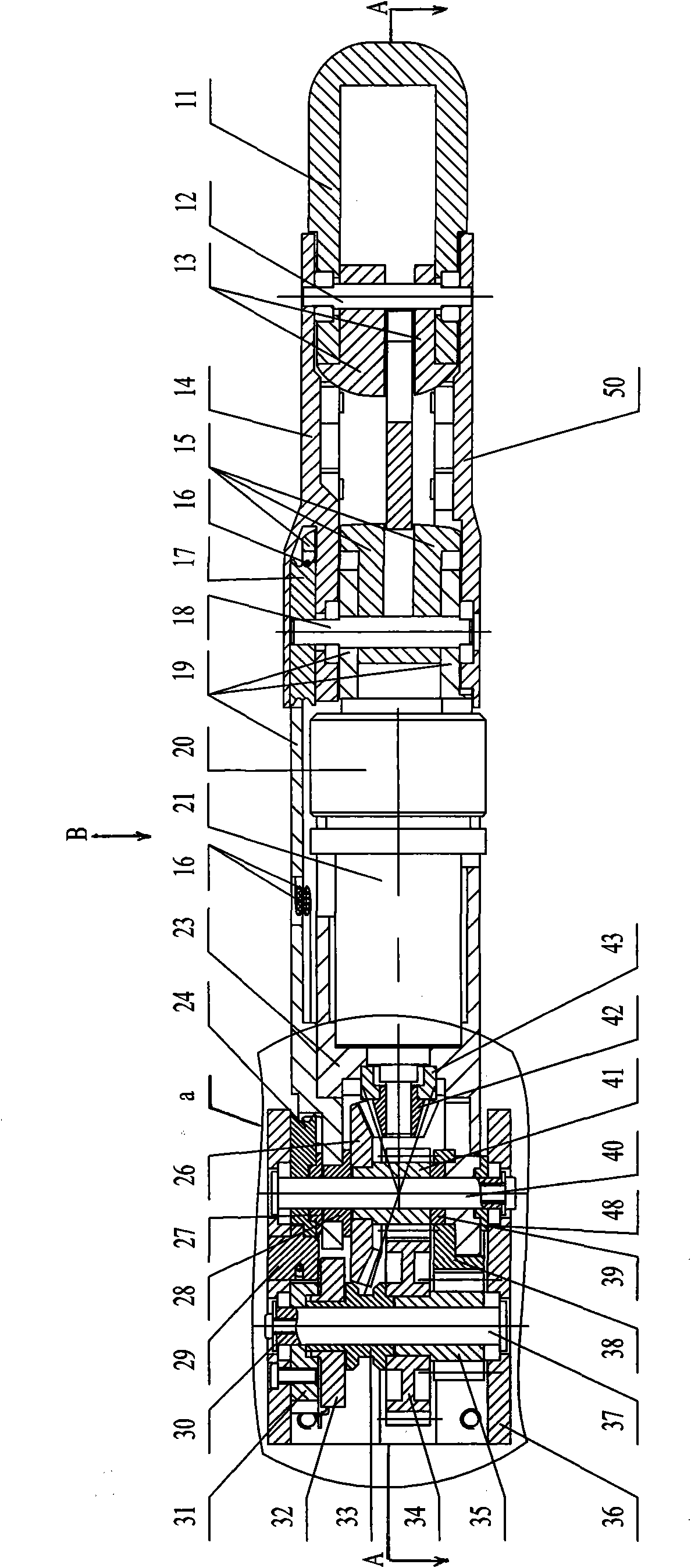
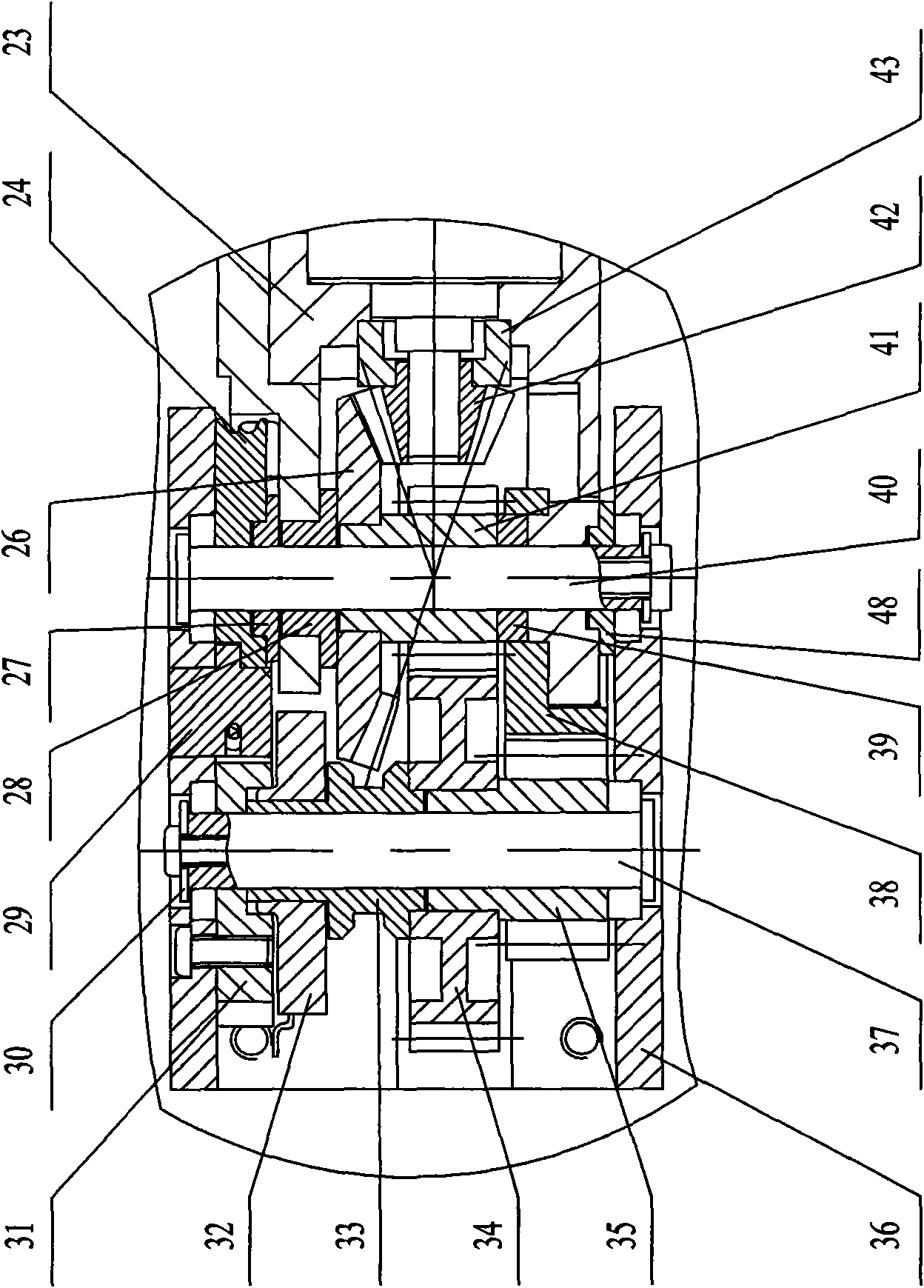
[0007] Specific implementation mode one: combine Figure 1 to Figure 6 Describe this embodiment, the motor built-in artificial finger of this embodiment comprises miniature disc type brushless motor 20, transmission mechanism and finger mechanism, and described transmission mechanism is made up of planetary reducer 21, small bevel gear 42, first slide bearing 43, Large bevel gear 26, connecting rod 6, pretension sheave 24, transmission sheave 17, two wire ropes 16, wire rope pretension block 29, second sliding bearing 27, second shaft 37, fifth sliding bearing 39, four Wire rope connection ball 44, the first small spur gear 41, the first large spur gear 34, the second small spur gear 35 and the second large spur gear 38, the finger mechanism includes a base 1, a first shaft 40, a third Shaft 18, the 4th shaft 12, the 3rd slide bearing 48, the 4th slide bearing 28, base phalanx, middle phalanx and far phalanx 11, described base phalanx is by the base phalanx left side board 23 ...
specific Embodiment approach 2
[0008] Specific implementation mode two: see figure 1 and image 3 , the motor built-in artificial finger of the present embodiment is also added with a position sensor, the position sensor is composed of a potentiometer 32, a sliding bearing 33 and a potentiometer connecting plate 31, and the potentiometer connecting plate 31 is set on the second shaft 37 And fixed on the inner wall of the base 1, the potentiometer 32 is fixed on the potentiometer connecting plate 31 and connected with the second shaft 37 through the sliding bearing 33, the lower end of the sliding bearing 33 is fixed with the first large spur gear 34 catch. With such setting, the absolute position of the base joint can be obtained through conversion of the voltage change of the potentiometer. Other compositions and connections are the same as in the first embodiment.
specific Embodiment approach 3
[0009] Specific implementation mode three: see Figure 4 , the motor-built-in prosthetic finger of this embodiment is also added with a torque sensor, and the torque sensor is composed of two strain gauges 49, and the two strain gauges 49 are symmetrically attached to the left side plate 23 of the base knuckle along the axis of the prosthetic finger superior. In this way, the torque can be obtained through the conversion of the change of the strain gauge. The strain gauges are symmetrically attached to the moment-sensitive part of the left plate of the base knuckle, and the moment-sensitive part of the left plate of the base knuckle is the part that bears all the torque of the finger. Other compositions and connections are the same as those in the second embodiment.
PUM
 Abstract
Description
Claims
Application Information
 - R&D
- Intellectual Property
- Life Sciences
- Materials
- Tech Scout
- Unparalleled Data Quality
- Higher Quality Content
- 60% Fewer Hallucinations
Browse by: Latest US Patents, China's latest patents, Technical Efficacy Thesaurus, Application Domain, Technology Topic, Popular Technical Reports.
© 2025 PatSnap. All rights reserved.Legal|Privacy policy|Modern Slavery Act Transparency Statement|Sitemap|About US| Contact US: help@patsnap.com


