Numerical-control machine tool for processing spiral bevel gear

A technology for spiral bevel gears and machine tools, applied in gear cutting machines, metal processing equipment, gear tooth manufacturing devices, etc. problems, to achieve the effect of compact structure, reduced size, and high tool positioning accuracy

Inactive Publication Date: 2009-09-23
HUNAN ZDCY (ZHONGDA CHUANG YUAN) CNC EQUIP CO LTD
View PDF0 Cites 11 Cited by
  • Summary
  • Abstract
  • Description
  • Claims
  • Application Information

AI Technical Summary

Problems solved by technology

The traditional CNC spiral bevel gear processing machine tool has the following problems due to the defects in the overall structural design: see the attached figure 1 , the traditional CNC spiral bevel gear processing machine tool, the center of gravity of the workpiece box does not coincide with the center of rotation, forming an offset structure, the radius of rotation is large, and a large centrifugal force is generated when the B-axis rotates, which affects the stability of the workpiece box movement In addition, due to the large radius of gyration, the size of the bed and slide table supporting the workpiece box is large, and the span of the guide rail moving in the Z direction is large, which makes the rigidity of the support of the workpiece box higher and increases the manufacturing cost of the machine tool; at the same time, The CNC spiral bevel gear processing machine tool with a traditional structure adopts a structure in which the center of gravity of the workpiece box is offset from the center of rotation, so that the rotation angle of the workpiece box is small, and the rotation angle is only between -5 degrees and 90 degrees. When the rotation angle is At -5 degrees, the workpiece box and the sliding table below are likely to interfere with the relevant parts of the tool, which affects the normal operation and operation of the machine tool
See attached figure 2 , the traditional CNC spiral bevel gear processing machine tool, the supporting column of the tool box is a single-arm type, the tool box moves up and down in a cantilever shape on one side of the column, and the center of gravity is in an offset state. When the tool box moves, its gravity will generate a subversive moment , affecting the stability and positioning accuracy of the up and down movement of the tool box

Method used


Image

  • Numerical-control machine tool for processing spiral bevel gear
  • Numerical-control machine tool for processing spiral bevel gear
  • Numerical-control machine tool for processing spiral bevel gear

Examples


Embodiment Construction

[0016] The specific structure of the present invention will be described in detail below in conjunction with the examples.

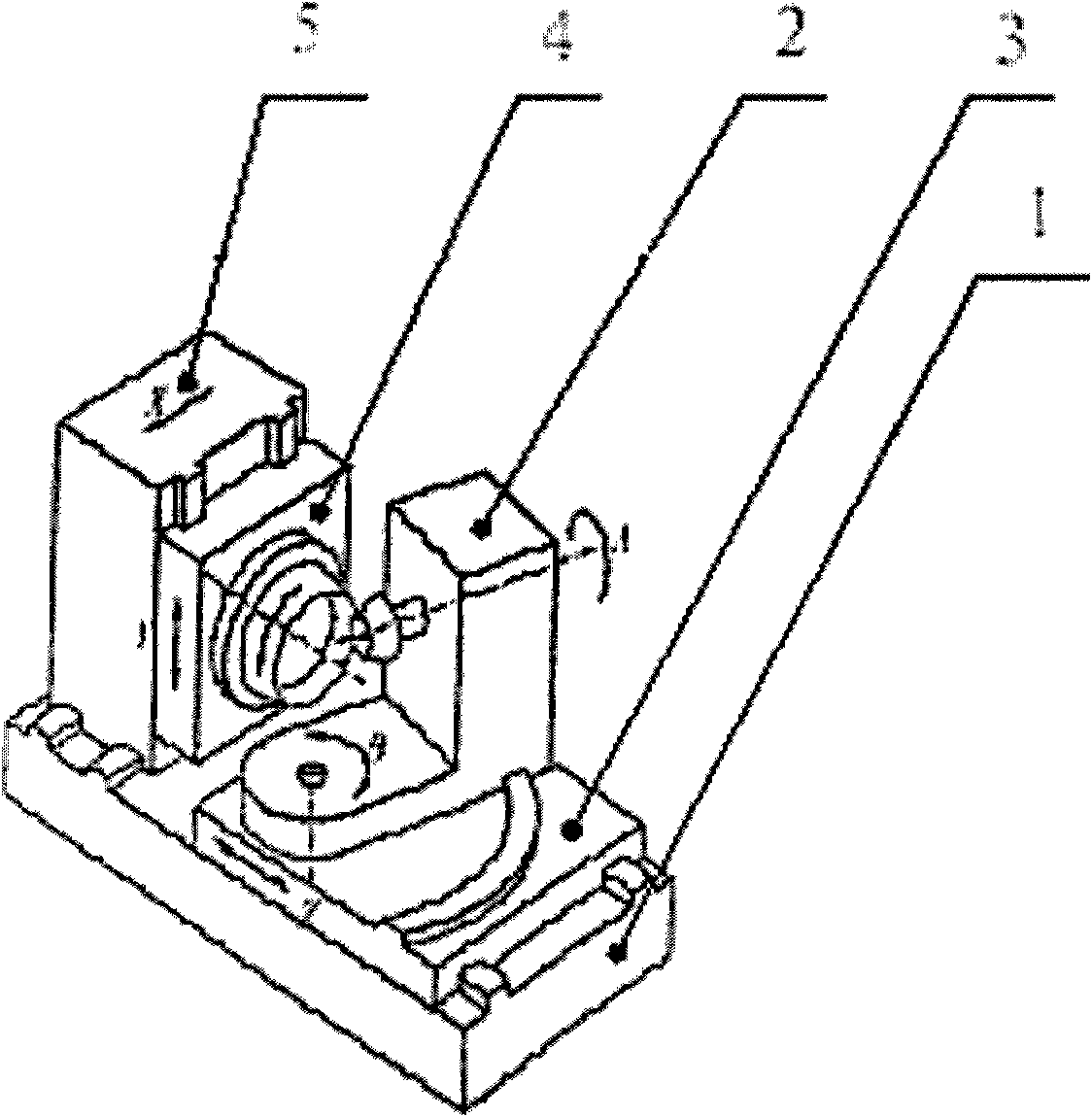
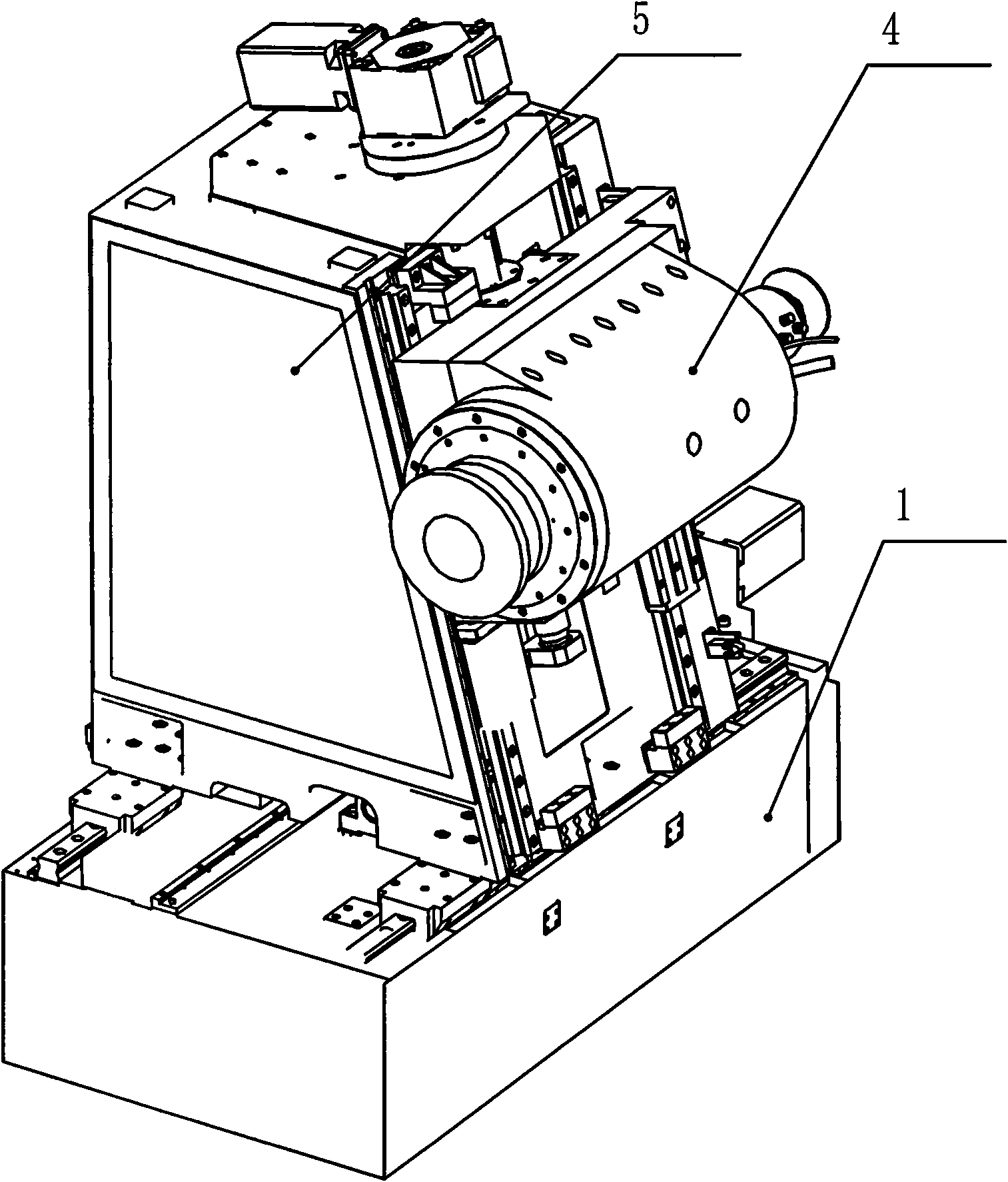
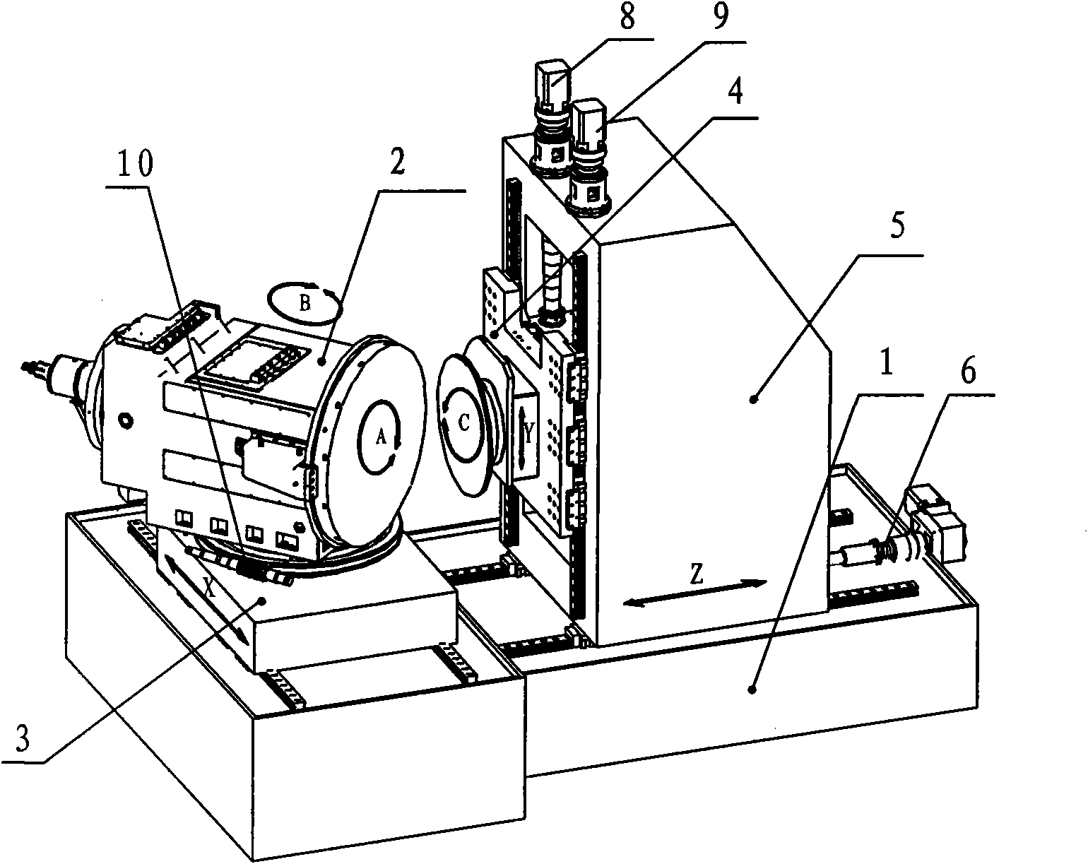
[0017] See attached image 3 , a CNC spiral bevel gear processing machine tool according to the present invention, comprising a bed 1, a workpiece box 2, a workpiece box turntable 3, a tool box 4, and a tool box supporting column 5; the bed 1 is T-shaped, and on the plane of the bed There are two sets of mutually perpendicular tracks X, Z, the workpiece box turntable 3 is installed on the track X and can slide along the axial direction of the track X; the tool box support column 5 is installed on the track Z And it is pulled by the screw mandrel 6 to slide axially along the track Z; the workpiece box 2 is installed on the workpiece box turntable 3 through the turntable bearing 7, and the axis center of the turntable bearing 7 is in line with the center of gravity of the workpiece box 2 Coincident; the tool box support column 5 is a gantry structure, and...


PUM


Abstract

The invention provides a numerical-control machine tool for processing spiral bevel gear, which comprises a machine tool body, a workpiece box, a turn table of the workpiece box, a tool box and the supporting post of the tool box, wherein, the machine tool body is T-shaped, and two groups of rails X and Z which are perpendicular to each other are formed on the machine tool body; the turn table of the workpiece box is mounted on the rail X; the supporting post of the tool box is mounted on the rail Z; the workpiece box is mounted on the turn table thereof via turntable bearings; the supporting post of the tool box has a gantry structure, the sliding rail Y of the tool box is formed on one side of the gantry, and two traction screw rods are arranged in the gantry; and screw holes are formed on the tool box, the tool box is rotationally mounted on the traction screw rods via the screw holes, and one end of the tool box is stuck to the rail Y via slideway. The invention has the following advantages: the structure is reasonable, the operation and the application are convenient, the workpiece box has a small turning radius and large turning angle, the machine tool has small volume and stable operation, and the tool has high positioning accuracy, so that the invention is applicable to industrialized production, in particular to the numerical-control processing of large-size spiral bevel gear.

Description

technical field [0001] The invention discloses a numerical control spiral bevel gear processing machine tool, which belongs to the field of numerical control machine tool processing. Background technique [0002] CNC spiral bevel gear processing machine tools are widely used in the field of spiral bevel gear processing because of their high cutting efficiency and high processing accuracy. The traditional CNC spiral bevel gear processing machine tool has the following problems due to the defects in the overall structural design: see the attached figure 1 , the traditional CNC spiral bevel gear processing machine tool, the center of gravity of the workpiece box does not coincide with the center of rotation, forming an offset structure, the radius of rotation is large, and a large centrifugal force is generated when the B-axis rotates, which affects the stability of the workpiece box movement In addition, due to the large radius of gyration, the size of the bed and slide table...

Claims


Application Information

Patent Timeline
IPC IPC(8): B23F9/00B23F23/00
Inventor 阳益江丁志文陈敢
Owner HUNAN ZDCY (ZHONGDA CHUANG YUAN) CNC EQUIP CO LTD
Why Eureka
Try Eureka