Improved automatic control hydraulic drive oil pumping machine

A technology of hydraulic transmission and pumping unit, which is applied in transmission devices, fluid transmission devices, mechanical equipment, etc., can solve the problems of low service life of seals, large area of ​​hydraulic cylinders, and unsatisfactory energy-saving effect, and achieves the improvement of mechanical Performance, safe and reliable performance, good energy saving effect

Active Publication Date: 2009-09-23
宋志亮
View PDF4 Cites 21 Cited by
  • Summary
  • Abstract
  • Description
  • Claims
  • Application Information

AI Technical Summary

Problems solved by technology

The stroke control rod installed on the side of the hydraulic cylinder is equipped with symmetrical stoppers. The motorized reversing valve on the hydraulic control circuit cooperates with the stoppers, and hydraulic transmission is used instead of mechanical transmission. Its structure is relatively compact and its weight is light. It can reduce the manufacturing cost, but the horizontally fixed hydraulic cylinder occupies a large area, the piston rod and the lip of the cylinder will be eccentrically worn, and the service life of the seal will be low
Without balance counterweight, the energy-saving effect is not ideal, and the workover needs to be coordinated with a crane, which is inconvenient for the workover operation

Method used


Image

  • Improved automatic control hydraulic drive oil pumping machine
  • Improved automatic control hydraulic drive oil pumping machine
  • Improved automatic control hydraulic drive oil pumping machine

Examples


Embodiment Construction

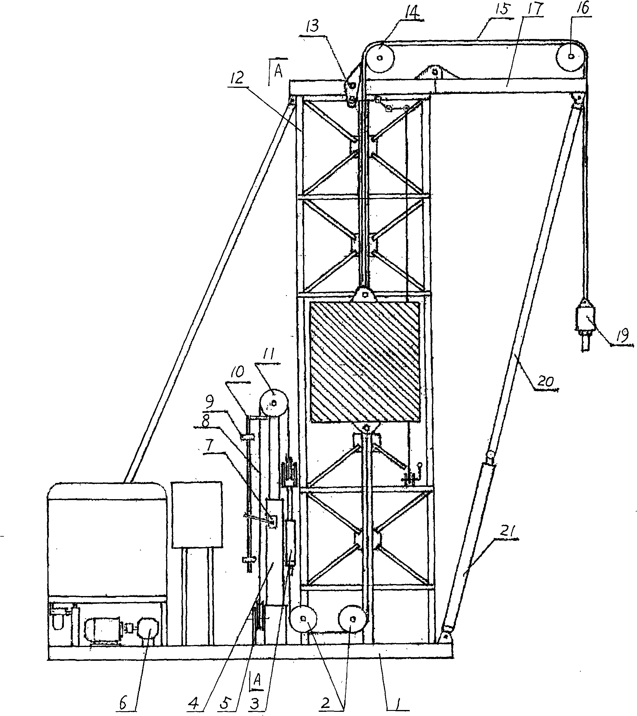
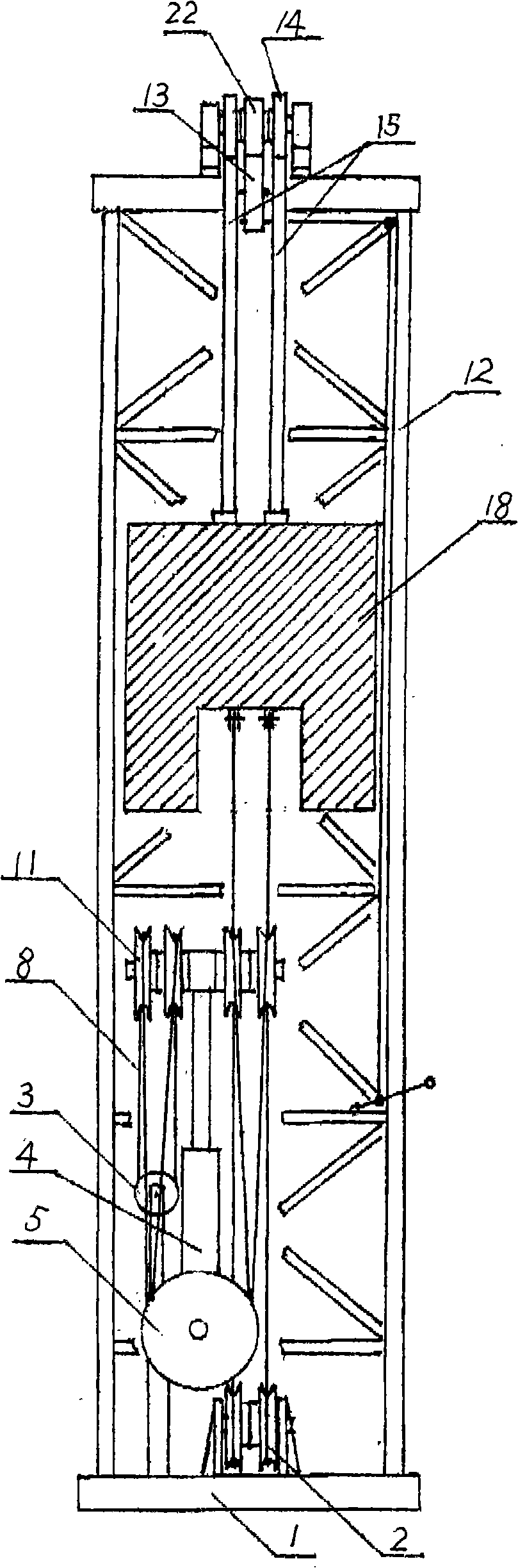
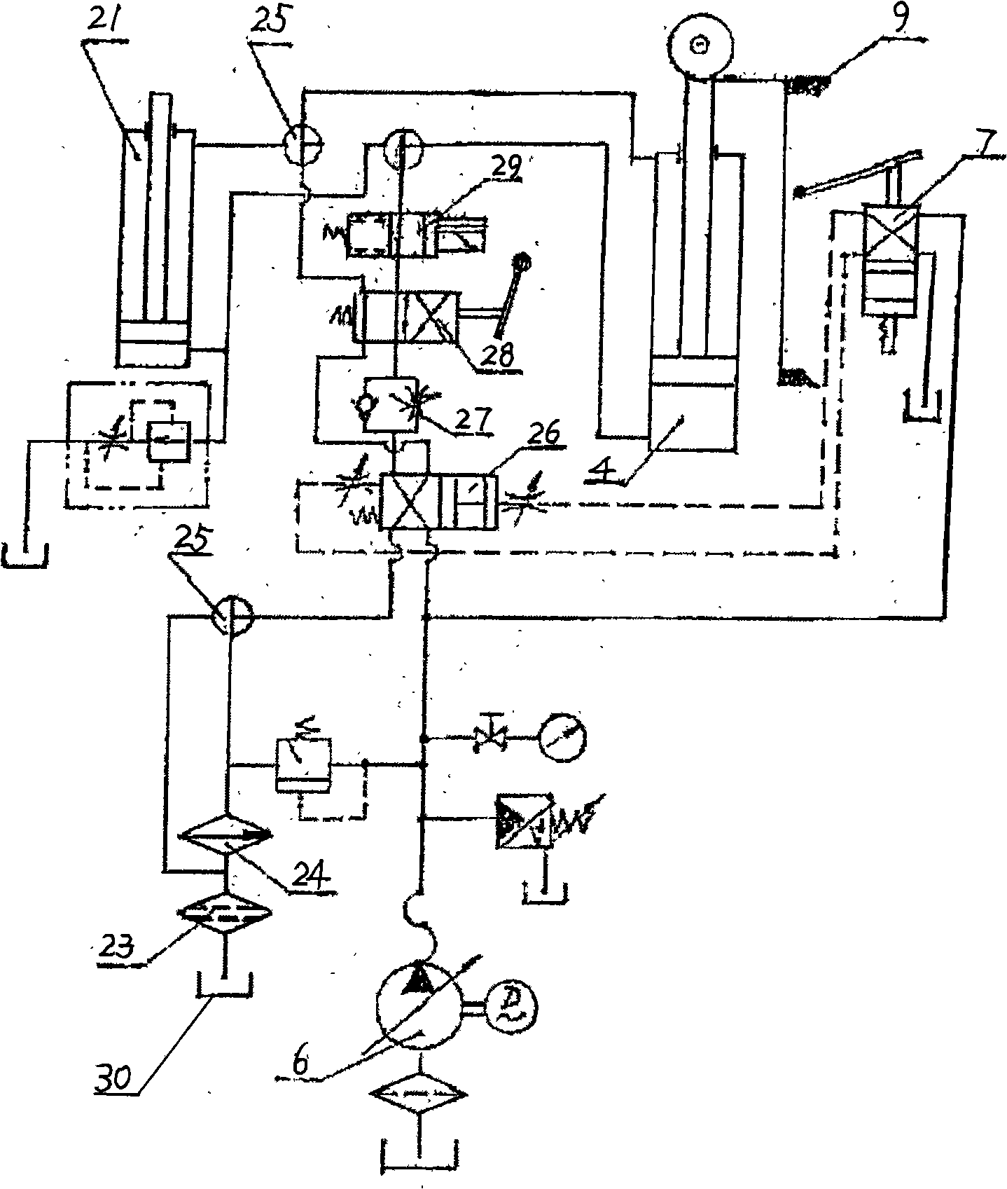
[0010] An improved automatic control hydraulic transmission pumping unit, such as figure 1 , figure 2 , image 3 As shown, it includes a hydraulic cylinder installed on the hydraulic circuit and a motorized reversing valve 7 is arranged on the hydraulic cylinder 4, and a symmetrical stroke adjustment block 9 is arranged on the stroke controller 10 installed at the end of the piston rod of the hydraulic cylinder 4 , the control arm of the motorized reversing valve 7 cooperates with the symmetrical block 9, and the upright hydraulic cylinder 4 and the support frame 12 are fixed on the machine base 1, the movable pulley 11 is installed on the top of the piston rod of the hydraulic cylinder 4, and the support frame 12 The sprocket wheel 14 with safety locking device is installed on the upper platform. The safety locking device is a ratchet mechanism, and a ratchet 22 is fixed on the sprocket shaft, and the ratchet 13 installed on the platform on the support frame 12 cooperates ...


PUM


Abstract

The invention discloses an improved automatic control hydraulic drive oil pumping machine. A machine base is fixedly provided with an upright hydraulic cylinder and a support frame; the top part of a piston rod of the hydraulic cylinder is provided with a moving pulley; an upper platform of the support frame is provided with a chain wheel, and the outer side of the upper platform is hinged with afront platform with a guide chain wheel; a lifting oil cylinder is hinged with the machine base, and a piston rod of the lifting oil cylinder is hinged with the front platform; one end of wire rope is connected with a wire rope adjuster, and the other end is connected with the bottom part of a balancing tank by the moving pulley of the hydraulic cylinder through a fixed pulley of the machine base; a chain connected with the top part of the balancing tank is connected with a polished rod eye by the chain wheel and the guide chain wheel; an oil channel between a variable oil pump on the hydraulic circuit and the hydraulic cylinder is provided with a liquid control reversing valve, a one-way throttle valve, a hand operated reversing valve, an electromagnetic valve and a three-way rotary diskvalve in sequence, and the oil charging channel and the oil discharging channel of the hydraulic cylinder are connected with the lifting oil cylinder by the three-way rotary disk valve respectively. The oil pumping machine is small in volume, low in energy consumption, good in energy saving effect, reliable in performance and convenient in use, and can conveniently solve a space problem for well repair without moving the main machine during well repair.

Description

technical field [0001] The invention belongs to oil exploitation equipment, in particular to an improved automatic control hydraulic transmission pumping unit. Background technique [0002] At present, the pumping equipment used for oilfield exploitation generally adopts the traditional mechanical transmission pumping unit. However, its structure is huge and heavy, and it is difficult to adjust the stroke and adjust the balance. Oilfields generally use long-stroke oil well pumps to improve efficiency. Due to structural problems, large horse-drawn carts are used to increase the stroke of mechanically driven oil pump units in order to meet the needs of long-stroke oil well pumps, which greatly increases power consumption and low power transmission efficiency. At present, a hydraulic transmission pumping unit has been developed. Its structure is: a hydraulic cylinder is fixed horizontally on the frame, a movable pulley is installed at the end of the piston rod, and one end of ...

Claims


Application Information

Patent Timeline
Patent Type & Authority Applications(China)
IPC IPC(8): E21B43/00F16H47/02
Inventor 宋志亮
Owner 宋志亮
Why Eureka
Try Eureka