Coiler

A winder and guide plate technology, applied in the direction of fixing labels, labels, external supports, etc., can solve the problems of bobbin deformation, small contact area, etc.

Inactive Publication Date: 2009-09-30
MAX CO LTD
View PDF0 Cites 8 Cited by
  • Summary
  • Abstract
  • Description
  • Claims
  • Application Information

AI Technical Summary

Problems solved by technology

However, since the outer peripheral portion of the guide plate on one side of the bobbin has a small contact area, the generation of abrasive powder and the deformation of the bobbin due to the wear of the bobbin may sometimes occur.
Therefore, most of the bobbins are made of plastic, which poses a problem in terms of disposal.
In addition, conventional guide plates on both sides are often formed in the same shape.

Method used


Image

  • Coiler
  • Coiler
  • Coiler

Examples


Embodiment 1

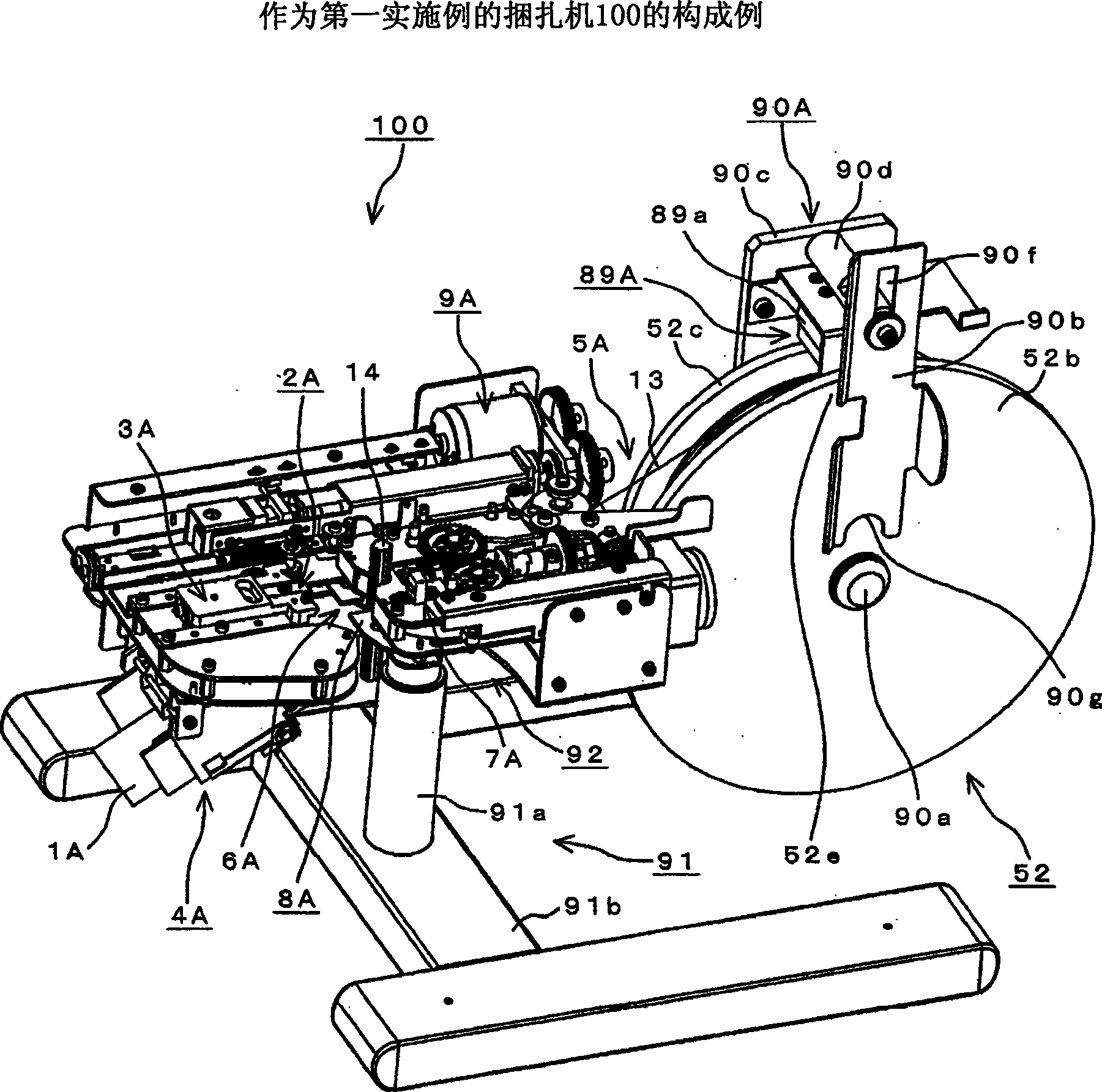
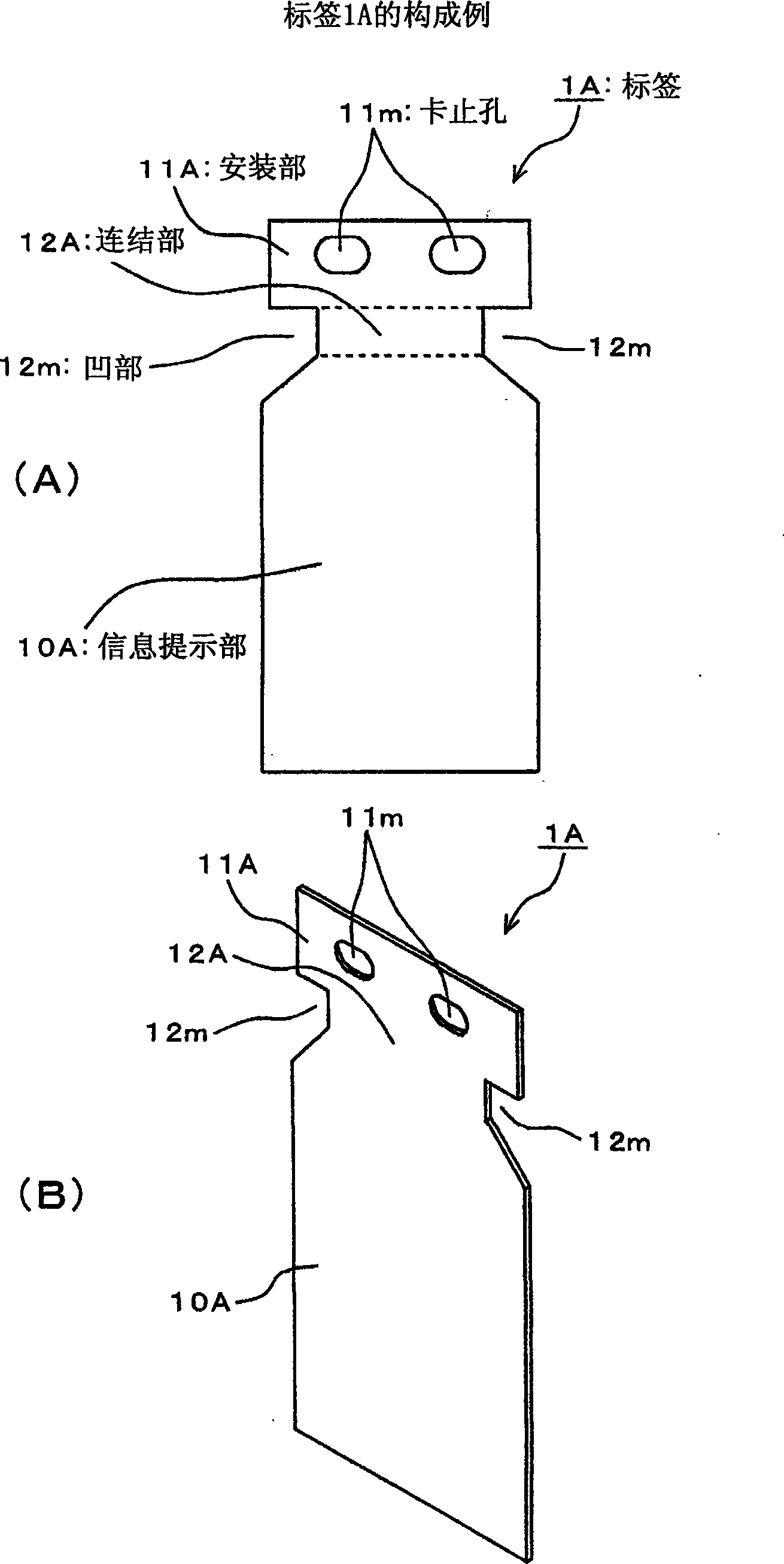
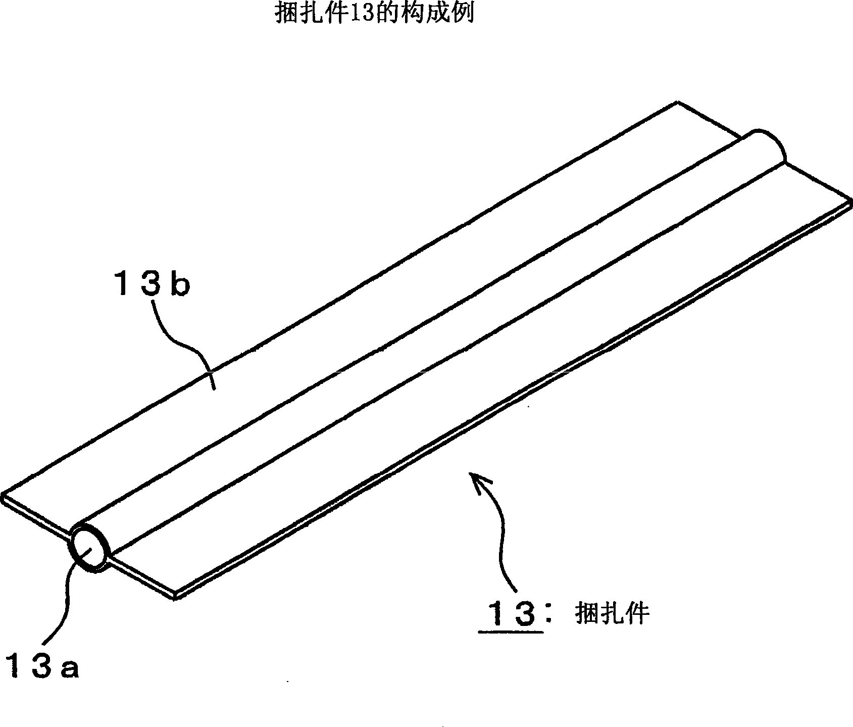
[0083] figure 1 It is a perspective view which shows the structural example of the binding machine 100 which is 1st Example of this invention. figure 1 The shown binding machine 100 uses the two locking holes provided on the label 1A, etc., to pass a band-shaped binding member 13 such as a cable tie, and at the same time, wrap the binding member 13 around the bag with the mouth tightly closed. 14 etc. (refer to Figure 5 ) to attach the label. The bag 14 constitutes an example of a loaded object. As the binding member 13, strings, metal wires, etc. are used in addition to cable ties.

[0084] The binding machine 100 is provided with the main body frame part 92 which comprises a main body part, and the support part 91 which supports this main body frame part 92. As shown in FIG. The support part 91 is comprised from the support stand 91b of "H" shape, and the support|pillar 91a vertically attached to this support stand 91b. The main body frame part 92 is attached to the ...

Embodiment 2

[0397] Figure 59 It is a partially enlarged perspective view showing a configuration example of a label spring loading mechanism 2A' of the binding machine 200 as the second embodiment.

[0398] Figure 59 The illustrated strapping machine 100 is provided with a tag spring loading mechanism 2A'. The label spring loading mechanism 2A' is equipped with a pair of torsion spring (Neuribane) members 21, 22 constituting one example of the push-in member, which are pressed from both sides to the binding member fastening mechanism from the label conveying mechanism 4A via the label holding mechanism 3A. 7A operates in such a way that the side end of the label 1A conveyed by the binder forming mechanism 6A is adjacent.

[0399] In this example, the upper end of the label 1A is held by the label carrying member 30e provided at a predetermined position from the upper part of the label holding mechanism 3A to the binder passage 303, and at the same time, the side ends of the label 1A a...


PUM


Abstract

The present invention provides a coiler which can increase the braking force of the coiler and can restrain the coiler abrasion and deformation caused by the braking. The coiler is provided with a bobbin (52) which has a disc outside plate (52b) that is formed to a large shape compared with a disc inner plate (52c). A braking mechanism (89A) clamps a large-shaped part (52e) of the disc outside plate (52b) that has a shape larger than that of the disc inner plate (52c) for braking the bobbin (52). In an embodiment of the invention, the braking mechanism (89A) clamps the disc outside plate (52b) through a braking disc (90h) and a pressure lever (90b) of a solenoid (89a) in power failure.

Description

technical field [0001] The present invention relates to a winder that can be attached to a binding machine that winds a wire-shaped binding material on an attached object such as a package with a closed bag mouth and a bundle of wire rods bundled together. Specifically, a winder having a second guide plate having a larger shape than the first guide plate is provided, and the brake mechanism cooperates with the large shape portion constituting the second guide plate which is larger in shape than the first guide plate. The winder is braked, so that it is possible to appropriately brake the rotation of the winder caused by the pulling out of the binding material accompanying the binding operation, and to suppress the wear and deformation of the winder caused by the braking action. . Background technique [0002] Conventionally, in order to close the mouth of the bag or bundle the wires, a binding material generally called a wire tie, which is formed by wrapping a plastic thin ...

Claims


Application Information

Patent Timeline
Patent Type & Authority Applications(China)
IPC IPC(8): B65B51/08B65B13/02B65B13/18B65B27/06B65C7/00B65C9/00
Inventor 间庭良浩田口聪
Owner MAX CO LTD
Why Eureka
Try Eureka