Cold rolled material production equipment and cold rolling method

A technology for manufacturing equipment and rolling mills, applied in the field of cold-rolled material manufacturing equipment and cold-rolling, can solve problems such as residues and reduce the reliability of joints, and achieve the effects of high yield, excellent effect and high efficiency

Active Publication Date: 2009-10-07
PRIMETALS TECHNOLOGIES JAPAN LTD
1 Cites 12 Cited by

AI-Extracted Technical Summary

Problems solved by technology

In addition, there is a problem that with the increase in the number of joints, an increase in the number of fractures of the joint is expected, and it is necessary to reduce the number of j...

Method used

Here, examples of the first rolling mill 10a and the second rolling mill 10b include a four-high rolling mill, a six-high rolling mill (six-high rolling mill), and a pair cross rolling mill. rolling mill, 18-high Z-high rolling mill, 20-high Sendzimir rolling mill, multi-roll rolling mill (cluster), 12-high Ron type multi-roll rolling mill, etc., suitably cited Six-high rolling mill. By applying the six-high rolling mill to the first rolling mill 10a and the second rolling mill 10b, it is possible to reduce the roll bending deformation variation caused by the fluctuation of the rolling load accompanying the increase of the coefficient of friction during low-speed rolling, Thus, the strip shape can be stably controlled. As a result, cracking and pinching can be reduced, and rolling can be stabilized. In addition, by configuring two first rolling mills 10a and second rolling mills 10b, it is suitable for medium-scale production with an annual output of about 600,000 ton to 900,000 ton.
In addition, by rolling speed control device 40, make joint and the rolling speed near this joint be more than 0mpm and below 50mpm, preferably more than 0mpm and below 10mpm, more preferably more than 0mpm and below 5mpm, Furthermore, it is preferably more than 0 mpm and less than 2 mpm. By applying the above-mentioned thickness control and shape control in the low-speed region, the timing of the start and end of the dynamic gauge control can be made close to the front of the joint point, so that it becomes a non-standard dynamic Variation control range is minimized.
In addition, in the pass for the first time, the number of joining and cutting times of the strip end of the leading coil 22a (25b) after the second pass and the strip front end of the trailing coil 22b are reduced, The splicing time and cutting time corresponding to the reduced number of times are used as the rolling time, and coil build-up in which several coils are used as one coil is performed in order to increase annual production.
In addition, utilize the rolling speed control device 40 to make the rolling speed of the joint and the vicinity of the joint be more than 0 mpm and less than 50 mpm, preferably more than 0 mpm and less than 10 mpm, more preferably more than 0 mpm and less than 5 mpm, and then It is preferably more than 0 mpm and less than 2 mpm, and the above-mentioned thickness control and shape control in the low-speed region can be applied, thereby enabling the start and end timing of on-the-fly gage changing to be close to In front of the junction, thereby minimizing the control range of the non-standard dynamic variable gauge.
In the rolling during splicing, the rolling speed during splicing of the strip end of the leading coil 22a (25b) and the strip leading end of the trailing coil 22b is controlled by the rolling speed control device 40. 50 mpm or less, preferably 20 mpm or less, more preferably 10 mpm or less, further preferably 5 mpm or less, and more preferably 2 mpm or less at a low speed, shorten the length of the strip stored in the strip storage device 50, and pass the tension generated by the tension generating device 60, 70 Control to suppress the increase in rolling load.
In this cold-rolled material manufacturing equipment 100, since the coil is transported from the coil coiling device 24 to the coil unwinding device 21a, 21b as described above, and is continuously cold-rolled multiple times until reaching the desired product Therefore, the range of the thickness of the strips S to be joined by the joining device 23 is not less than 0.1 mm and not more than 6.0 mm. Compared with the prior art, the range of the joining thickness is wider. Furthermore, the minimum joining plate thickness is 1.0mm or less, and compared with conventional PL-TCM and TCM, joining is performed in a thinner plate area.
The coils after several coils of the first rolling pass after splicing are completed, as long as there is a surplus in the strength of the joint, the joint also carries out the same rolling as the rolling of the normal part, When there is no margin in the strength of the joint, or when the thickness ratio of the joined joint exceeds 1:1.5, or when the difference in thickness of these coils exceeds 1 mm, the FGC is used for joining. After maintaining the joint strength, when the rolling is finished, the strip cutting device 28 is used to cut off the next coil, and the coil coiling device 24 is used for coiling. By using the coil coiling device 24 as a Calense coiler as described above, it is only necessary to reduce the exit rolling speed at the time of cutting to about 150 mpm, and since the number of joints is reduced, the throughput is improved. .
The strip storage device 50 configured between the joining device 23 and the first rolling mill 10a, in the above-mentioned low-speed region, respectively stores less than 100m in length, is suitable for storing less than 50m, is more suitable for storing less than 20m, and then is suitable for storing 10m or less, further suitable for storing strips S of 5m or less. Thus, the strip S can be rolled continuously by discharging the strip S of the above-mentioned length previously stored in the strip storage device 50 while the strip S is joined by the joining device 23 . In addition, by configuring the shortened strip stocker 50, the length of the entire facility can be shortened, thereby reducing facility construction costs.
[0091] Under low-speed rolling conditions, the coefficient of friction between the work rolls and the strip increases, and as a result, the rolling load may increase. Therefore, the tension generated by the tension generating device arranged on the entry and exit side of the rolling mill is absorbed into the thickness control, and the tension control is performed so as to achieve a desired thickness, thereby suppressing an increase in the rolling load.
[0092] In the actual results (actual results) of PL-TCM equipment, even in the case of using FBW and LBW, when there is a thickness difference between the end of the leading coil and the front end of the following coil, due to the There is a step difference in the part, so there is an impact force during rolling, and there is a problem that the probability of ...

Abstract

In a cold rolled material production equipment, a strip storage device (50) is provided. The strip storage device (50) is disposed between connection means (23) and rolling machines (10a, 10b). The connection means (23) connects the tail end of a preceding coil (25b), disposed on the exit-side of an unwinding device (21a) for unwinding a hot rolled coil after pickling, to the leading end of a following coil (22a) unwound from the unwinding device. The strip storage device (50) stores a strip S for continuously carrying out rolling by the rolling machines during the connection of the precedingcoil to the following coil by the connection means. The rolling machines (10a, 10b) roll the preceding and following coils, in such a state that the tail end of a preceding coil (25b) has been connected to the leading end of a following coil (22a), unidirectly in a continuous manner. The cold rolled material production equipment further comprises a strip cutting device (28) for cutting the strip into desired length, a winding device (24) for winding the rolled coil, transfer means (30) for transferring the coil extracted from the winding device to unwinding devices (21a, 21b) for repeatedly rolling the coil until the product sheet reaches a desired thickness, and a rolling speed control unit (40) for controlling the rolling speed during connection of the preceding coil to the following coil so that the rolling speed is lower than the steady rolling speed.

Application Domain

Measuring devicesRolling mill drives +4

Technology Topic

EngineeringRolling speed +3

Image

  • Cold rolled material production equipment and cold rolling method
  • Cold rolled material production equipment and cold rolling method
  • Cold rolled material production equipment and cold rolling method

Examples

  • Experimental program(1)

Example Embodiment

[0087] The function of the cold-rolled material manufacturing facility and the cold-rolling method of the embodiment of the present invention will be described below.
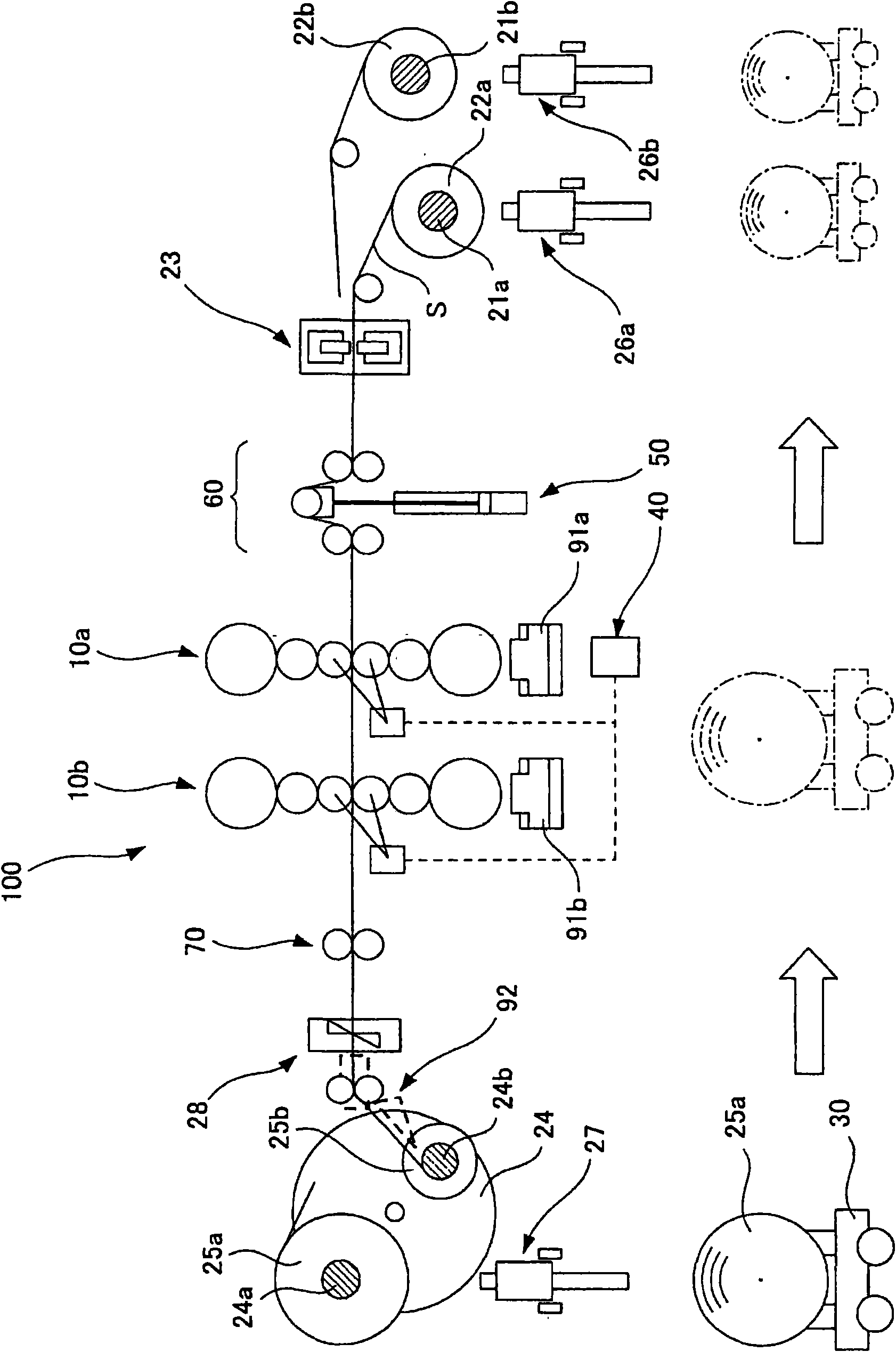
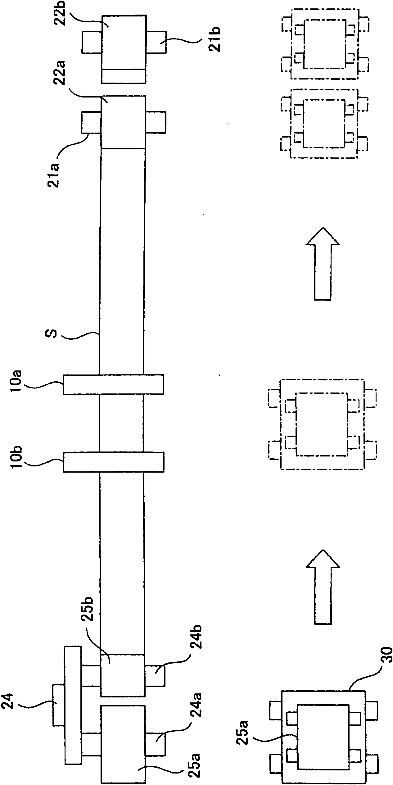
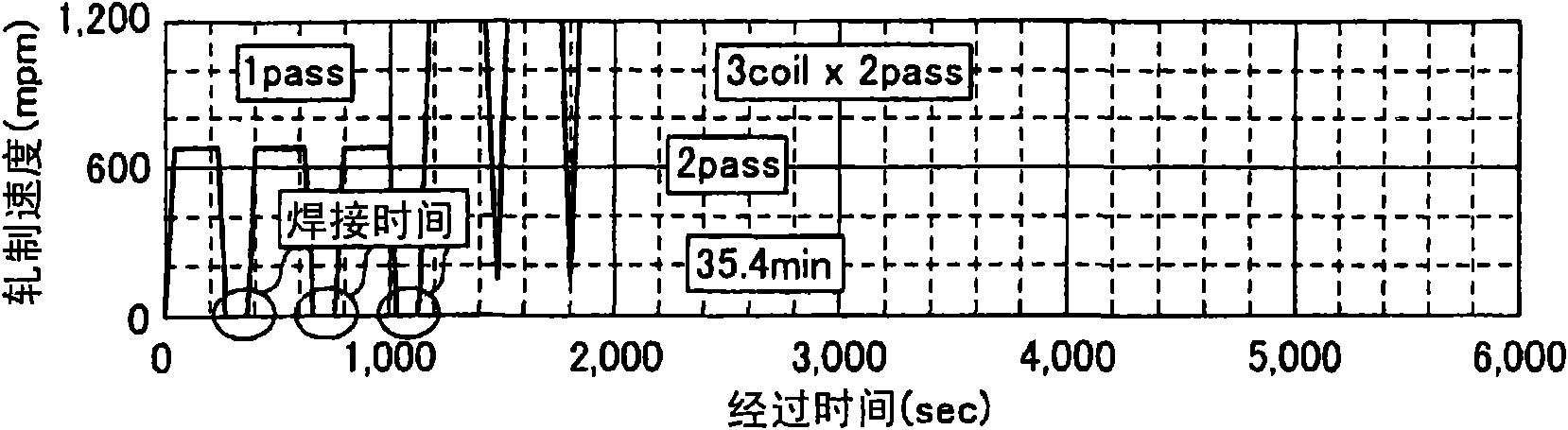
[0088] The rolling speed of the leading end of the preceding coil and the leading end of the following coil during joining is lower than the normal rolling speed, and the strip storage length of the strip storage device arranged between the joining device and the rolling mill is shortened , The device is miniaturized.
[0089] Under low-speed rolling conditions, the plate thickness is measured by a plate thickness gauge installed on the exit side of the rolling mill, and the plate thickness is corrected based on the deviation between the plate thickness command value and the actual plate thickness value. Right below the work roll, the time from rolling to the thickness detection is delayed, and the thickness control accuracy is reduced. Therefore, under low-speed rolling conditions, the incoming side rolling speed, incoming side plate thickness, and exit side rolling speed are measured, and based on these measured values, the plate thickness directly below the work roll of the rolling mill is calculated. The hydraulic pressing device provided in the rolling mill controls the thickness of the plate so as to achieve the desired thickness, thereby performing the thickness control without a time delay, and ensuring the accuracy of the thickness control.
[0090] Similarly, under low-speed rolling conditions, the shape of the strip is measured by the shape meter installed on the exit side of the rolling mill, and the shape control method is corrected based on the deviation between the shape command value and the actual shape value. Due to the time delay , Resulting in a decrease in the accuracy of shape control. Therefore, by detecting the fluctuation of the rolling load of the rolling mill, based on the calculation result of the roll deflection accompanying the fluctuation, in the case of no time delay, in the roll bender or cooling medium (coolant) control Or under the control of both of them, to control the shape of the strip, so as to ensure the accuracy of shape control. In addition, by making the rolling mill a six-high rolling mill, the amount of change in bending deformation of the work rolls and reinforcement rolls that accompany the fluctuation of the rolling load is compared with that of a conventional four-high rolling mill, etc., to significantly suppress and make The strip shape change when the speed is changed is minimized.
[0091] Under low-speed rolling conditions, the friction coefficient between the work roll and the strip increases, and as a result, the rolling load may increase. Therefore, the tension generated by the tension generating device arranged on the entry and exit side of the rolling mill is absorbed into the plate thickness control, and the tension control is performed to achieve the desired plate thickness, thereby suppressing the increase in the rolling load.
[0092] In the actual results (actual results) of the PL-TCM equipment, even when FBW and LBW are used, if there is a difference in thickness between the end of the preceding coil and the front end of the following coil, a step is generated at the joint. Due to the impact force during rolling, there is a problem that the probability of joint breakage increases dramatically. Although the plate thickness difference is limited to less than 1mm and the plate thickness ratio is limited to less than 1:1.5 for rolling However, it cannot solve the problem that the strip joint portion breaks during rolling at a frequency of once in 1000 times. On the other hand, even in the technology under the joining conditions within the thickness control, the probability of breakage is high. The technology of joining conditions and rolling conditions, by changing the plate thickness between travels (between travels), makes the reduction of the junction and the vicinity of the junction less than the reduction of the normal rolling part, thereby further reducing the junction The fracture probability of the part. In addition, by making the rolling speed at the junction and the vicinity of the junction exceed 0 mpm and below 50 mpm, the non-standard dynamic gauge control range is minimized.
[0093] Furthermore, in the case where the thickness ratio between the end of the preceding coil and the end of the succeeding coil exceeds 1:1.5, or in the case where the thickness difference exceeds 1 mm, the joint portion that cannot be rolled in the prior art is passed The dynamic gauge control makes the reduction of the joint and the vicinity of the joint less than the reduction of the normal rolling part, and makes the rolling speed of the joint and the vicinity of the joint exceed 0 mpm and below 50 mpm, thereby , The impact force during the rolling of the joint is alleviated, the desired joint strength is maintained, and the limitation of the joint thickness is alleviated, and the limitation of the coil operation such as the rolling execution order is greatly eased.
[0094] Butt-joining methods such as LBW and FBW require very high accuracy in the cutting part of the front and end of the coil. Without this accuracy, the fracture rate of the joint of the rolled material will increase significantly and the reliability will be reduced. .
[0095] On the other hand, since MSW is a method of overlapping strips for joining, it is different from the joining device of the butt joining method, and is superior in joining thin objects of 2 mm or less. However, when the rolling amount of the joint is 50% or more of the base material thickness in cold rolling, the diffusion joint formed at the edge of the nugget will open in the form of cracks due to the rolling, and the stress concentration factor will increase. , There is a problem that the fracture probability of the joint is sharply increased, but by adopting the joint rolling method, it can be applied to cold rolling equipment.
[0096] In the first rolling pass, a plurality of coils are joined to produce a rolled coil. In the second rolling pass to the rolling pass before the final, the rolled coils are rolled without dividing into the desired coil length. In the last rolling pass, the cutting device arranged on the exit side of the rolling mill is divided into a desired coil length, thereby reducing the number of joining times, the number of cutting times, and the number of coils to be circulated.
[0097] By arranging the unwinding device and the winding device adjacent to each other, the coil conveying device is miniaturized and the tact time for conveying the coil is shortened.
[0098] When the desired annual output is relatively small, after the end of the preceding coil is withdrawn from the unwinding device or at the same time as it is withdrawn, the rolling speed should be lower than the desired speed. On the other hand, the following coil should be inserted This unwinding device unwinds at a speed higher than the rolling speed, and the joining device makes it catch up with the preceding coil until the joining of these coils is completed, maintaining the rolling speed, and at the same time The strip preliminarily stored in the strip storage device arranged between the unwinding device and the rolling mill is discharged, thereby constituting an unwinding device.
[0099] When the desired annual output is relatively small, after the strip is cut by the cutting device or while cutting, the rolling speed should be lower than the desired speed. On the other hand, the coil is pulled out from the coiling device. , Using a guiding device arranged between the cutting device and the winding device to guide the front end of the following coil to the winding device, thereby forming a winding device.
[0100] In the case of further improving the production capacity of the equipment, the number of the unwinding device is two, or the coiling device is a carrousel reel or two tension reel. , Thereby shortening the time required for rewinding.
[0101] In the case of rolling non-ferrous metals such as aluminum alloys, copper alloys, and magnesium alloys, by setting the joining device as a friction stir welding machine, the reliability of the joining portion can be improved at a low cost.
[0102] In the case of an annual production capacity of 600,000 to 900,000 tons, the number of coil cycles can be reduced by setting the rolling mills to two, and the output of the main motor of the rolling mill is used during low-speed rolling. To increase the strip tension between the rolling mills and reduce the increase in the rolling load associated with the increase in the friction coefficient between the work roll and the strip. Similarly, in the case of normal rolling, the strip tension between the rolling mills is also increased to reduce the number of rolling.
[0103] Next, the cold-rolled material manufacturing facility according to the embodiment of the present invention will be described with reference to the drawings. The cold-rolled material of this embodiment will be described by taking a cold-rolled steel sheet as an example.
[0104] figure 1 It is a schematic front view of a cold-rolled material manufacturing facility according to an embodiment of the present invention, figure 2 It is a schematic plan view. Figure 3a , Figure 3b , Figure 3c , Figure 3d It is a time chart showing the relationship between the elapsed time of each cold-rolled material manufacturing facility and the rolling speed, Figure 4 It is a graph showing the non-standard rate of each cold-rolled material manufacturing facility. Figure 5 to Figure 8 It is a graph showing the shape control range of the four-high rolling mill and the six-high rolling mill at the normal rolling speed and the low-speed rolling speed.
[0105] In the case of a hypothetical annual output of 600,000 to 900,000 ton, a plurality of rolling mills are arranged on the cold-rolled material manufacturing facility 100. In this embodiment, two rolling mills 10a and 10b are arranged.
[0106] Such as figure 1 As shown, there are: two coil unwinding devices 21a, 21b, which unwind the pickled hot rolled coils 22a, 22b; a joining device (joining mechanism) 23, which is arranged in the coil unwinding device 21a On the exit side of 21b, the end of the preceding coil 25b and the front end of the following coil 22a or 22b unwound from the unwinding device 21a or 21b are joined; the first rolling mill 10a and the second rolling mill 10b share the same Two rolling mills, which are used as rolling mills to continuously cold-roll the strip S in the state where the front and end of the coil are joined in one direction; the strip storage device 50, which is arranged in the joining device 23 and the first rolling Between the mills 10a, in order to perform continuous rolling by the rolling mills 10a, 10b during the joining of the preceding coil 25b and the succeeding coil 22a or 22b by the joining device 23, the strip S is stored; The cutting device 28, which is arranged on the exit side of the second rolling mill 10b, cuts the rolled strip to a desired length; the Calence Coiler 24, which is a coil coil for coiling the strip Device; Coil conveying device (conveying mechanism) 30, which pulls out the coil 25a from the coil coiling device 24, and transports it to the coil in order to perform rolling several times until the thickness reaches the desired product thickness. Material coiling devices 21a, 21b; and a rolling speed control device 40, which controls the rolling speed of the end of the preceding coil 25b and the leading end of the following coil 22a or 22b during joining to be lower than the normal rolling speed speed.
[0107] The hot-rolled coils 22a, 22b after the above-mentioned pickling are inserted into the coil unwinding devices 21a, 21b by the entry side coil moving carts 26a, 26b, respectively. In addition, the rolled coils 25a, 25b are pulled out by the exit side coil moving cart 27.
[0108] The rolling speed control device 40 is a device that can control the rolling speed to exceed 0 mpm and 50 mpm or less, more preferably to exceed 0 mpm and 25 mpm or less, more preferably to exceed 0 mpm and 10 mpm or less, and more preferably to exceed 0 mpm and 5 mpm. Hereinafter, it is more preferable to control to a control device exceeding 0 mpm and 2 mpm or less.
[0109] As a result, the length of the strip stored in the strip storage device 50 can be shortened, and the overall length of the equipment can be shortened, so that the equipment construction cost can be reduced. Furthermore, the impact force during joint rolling can be alleviated, the desired joint strength can be maintained, and the limitation on the thickness of the joint plate can be alleviated, and the limitation on the use of coils such as the rolling execution order can be greatly alleviated. In addition, it is possible to shorten the non-standard length during dynamic variable regulation control.
[0110] However, in general, in low-speed rolling, in order to obtain the same product thickness as the normal rolling speed region, the friction coefficient between the work roll and the strip increases. Depending on the steel grade and deformation resistance of the strip, there is rolling When the load is rising. When this amount of increase is contained within the rated load of the rolling mill, a large rolling mill that increases the rated load is required, and there is a problem of increased equipment introduction costs.
[0111] Therefore, a study on the confirmation of the increase in the rolling load in the low-speed region of 50 mpm or less and the method of reducing it are conducted with ordinary steel. Regarding the relationship between the number of passes, the rolling speed, and the rolling load in the rolling test performed by the testing machine, the base material was rolled up to 10 passes. As a result, it was confirmed that the rolling load increased in the low-speed region in the second half of the pass where the deformation resistance value of rolling was increased.
[0112] In the second half of the rolling pass, the rolling load increases. In the region where the deformation resistance increases, the shape speed dependence becomes less. One of the reasons is that the change in the friction coefficient caused by the reduction of the rolling speed is directly expressed as the rolling Changes in the control load. Therefore, in order to suppress the increase in the rolling load, after increasing the tension on the entry and exit side of the rolling mill, it was confirmed as planned that the rolling load can be reduced. At the same time, the strip tension between the first rolling mill 10a and the second rolling mill 10b can also be increased to reduce the increase in rolling load.
[0113] Therefore, tension generators 60 and 70 are installed on the entry and exit side of the rolling mill, and the increase in rolling load is reduced by applying front and rear tension in the low-speed region of the second half of the pass where the deformation resistance increases. The tension generating devices 60 and 70 that generate tension on the strip S are respectively arranged in the front stage of the first rolling mill 10a and the rear stage of the second rolling mill 10b. As the tension generating devices 60 and 70, for example, a pinch roll or a bridle roll is exemplified, and each has a drive device and a control device.
[0114] Furthermore, the tension generator 60 on the entry side of the first rolling mill 10a outputs a desired tension to prevent the thickness and shape of the plate from becoming 0 due to the rear tension of the first rolling mill 10a during joining. Destabilization also exerts an effect. In addition, the tension generating device 70 on the exit side of the second rolling mill 10b outputs the desired tension to prevent the second rolling material from being cut during the cutting of the front (leading) coil and the secondary (back) coil. The destabilization of the plate thickness and shape due to the front tension of the rolling mill 10b becoming zero also exerts an effect.
[0115] In addition, the tension generating device 70 applies the required forward tension to the rolling of the second rolling mill 10b, and the tension generated by the coil coiling device 24 can be suppressed to only the tension required for coil coiling. The tightness of the coil is minimized, so that damage caused by slip between layers of the coil and bending of the inner diameter of the coil can be prevented.
[0116] In the rolling during joining, the rolling speed control device 40 is used to control the rolling speed of the strip end of the preceding coil 22a (25b) and the strip end of the following coil 22b during the joining to 50 mpm or less , Preferably 20 mpm or less, more preferably 10 mpm or less, still more preferably 5 mpm or less, and even more preferably low speed of 2 mpm or less. The length of the strip stored in the strip storage device 50 is shortened, and the tension control by the tension generating devices 60, 70 suppress Increase in rolling load.
[0117] The strip storage device 50 arranged between the joining device 23 and the first rolling mill 10a, in the above-mentioned low-speed area, respectively stores a length of 100m or less, preferably 50m or less, more preferably 20m or less, and further preferably 10m or less, It is further suitable to store strip S under 5m. Thereby, while the strip S is joined by the joining device 23, the strip S of the above-mentioned length stored in advance by the strip storage device 50 is discharged, so that the strip S can be continuously rolled. In addition, by configuring the shortened strip storage device 50, the length of the entire equipment can be shortened, and the equipment construction cost can be reduced.
[0118] Generally speaking, under low-speed rolling conditions, the thickness is measured by a thickness gauge installed on the exit side of the rolling mill, and the thickness is corrected based on the deviation between the thickness command value and the actual thickness value. , After rolling directly under the working rolls of the rolling mill, the time delay until the thickness is detected, resulting in a decrease in the accuracy of the thickness control. Therefore, under low-speed rolling conditions, the tension in front of the first rolling mill 10a and the tension behind the second rolling mill 10b are absorbed into the plate thickness control, and the entry side rolling speed, entry side plate thickness and Based on these measured values, the exit rolling speed calculates the thickness of the plate directly under the work rolls of the rolling mill, and controls the plate thickness by using the hydraulic pressure reduction devices 91a, 91b of the rolling mills 10a, 10b to achieve the desired thickness. The desired sheet thickness can achieve the same sheet thickness accuracy as that of the normal rolling speed region, that is, an accuracy level with a sheet thickness ratio of about 1% or less.
[0119] In addition, it is also possible to measure the thickness of the incoming side plate and control the plate thickness through feed forward control.
[0120] Here, as the first rolling mill 10a and the second rolling mill 10b, four high rolling mills, six high rolling mills (six high rolling mills), pair cross rolling mills, ten Eight-high Z-high rolling mill, 20-high Sendzimir rolling mill, multi-high rolling mill (cluster), twelve-high Ron-type multi-high rolling mill, etc., suitable for six-high rolling制机。 Machine. By applying a six-high rolling mill to the first rolling mill 10a and the second rolling mill 10b, it is possible to reduce the amount of roll bending deformation variation caused by the fluctuation of the rolling load accompanying the increase in the friction coefficient during low-speed rolling. Thus, the strip shape can be stably controlled. As a result, plate cracks, squeezing, etc. can be reduced, and stable rolling can be achieved. In addition, by configuring two first rolling mill 10a and second rolling mill 10b, it is suitable for medium-scale production with an annual output of about 600,000 tons to 900,000 tons.
[0121] Secondly, based on Figure 5 to Figure 8 Describes the effect when a six-high rolling mill is used, especially the effect when a six-high rolling mill with a roll shift function, that is, the HC rolling mill and the UC rolling mill is used.
[0122] As mentioned above, the biggest effect of applying a six-high rolling mill to a rolling mill is that the ability to dynamically correct the change in roll bending deformation caused by the change in rolling load during low-speed rolling through roll control is increased. , Which can stably control the strip shape. In addition, the six-high rolling mill has a feature that the amount of variation in the bending deformation of the work roll caused by the load fluctuation is also smaller than that of the four-high rolling mill.
[0123] Regarding the shape control of the strip, in order to clarify the application effect of the six-high rolling mill, compared with the four-high rolling mill, a shape simulation (simulation) is performed. The rolled material with a width of 1200mm is cold rolled from a base material of 2.0mm to a product thickness of 0.4mm through two passes. The rolling speed is in the range of 450mpm to 1200mpm under normal conditions, and under 2mpm under low speed, and used The minimum output value and maximum output value of the roll control of each rolling mill. The wider the width of the shape control ability range, the higher the ability to correct shape disorder and the more excellent the shape control ability. in Figure 5 to Figure 8 Indicates the result of the simulation.
[0124] Figure 5 It is a graph comparing the shape control ranges of a six-high rolling mill and a four-high rolling mill when the rolling speed is normal. Figure 6 It is a graph comparing the shape control ranges of a six-high rolling mill and a four-high rolling mill when the rolling speed is low. Figure 7 It is a graph comparing the rolling load and shape control range of the four-high rolling mill at normal and low speeds. Figure 8 It is a graph comparing the rolling load and the shape control range of the rolling speed of a six-high rolling mill at normal and low speeds. In these figures, the horizontal axis represents the number of rolling passes and the rolling mill, and the vertical axis represents the shape (I-unit). In addition, in Figure 7 and Figure 8 In the middle, the vertical axis on the right represents the rolling load.
[0125] Such as Figure 5 As shown, when the rolling speed is normal, the fact that the shape control range of the six-high rolling mill is significantly wider than that of the four-high rolling mill is clarified.
[0126] In addition, such as Figure 6 As shown, under the condition that the rolling load increases when the rolling speed is low, although the range is narrower than the normal shape control range, it is clear that the shape control range of a six-high rolling mill is comparable to that of a four-high rolling mill. The fact that the rolling mill is significantly wider than that.
[0127] Such as Figure 7 As shown, in a four-high rolling mill, when the rolling speed is compared between normal and low speeds, at low speeds, due to the increase in rolling load, the shape control range is significantly narrowed and the shape correction becomes insufficient. , The possibility that the occurrence of accidents such as the shrinkage of the strip cannot be suppressed is high.
[0128] On the other hand, such as Figure 8 As shown, in a six-high rolling mill, when the rolling speed is compared at normal and low speeds, it is the same as a four-high rolling mill. At low speeds, the shape control range becomes narrower than that at normal times. However, it has the required sufficient shape control ability, and has sufficient shape control ability relative to the rolling load fluctuation, which is proved in this simulation.
[0129] Therefore, it is clarified that the rolling mill suitable for the present invention is a six-high rolling mill.
[0130] In the verification test using the test device, based on the calculation result of roll deflection caused by the rolling load fluctuation, when the shape control adopting the roll bending control and the roll cooling medium control is applied, the shape meter confirms the normal rolling After the target shape and deviation amount, compared with the situation that the time delay and the shape disorder cannot be avoided in the correction method, the shape correction can be performed without the time delay, and it can be confirmed that a good value of 10I-unit or less is obtained. shape.
[0131] By providing two coil unwinding devices 21a, 21b, when the strip S is joined by the joining device 23, the waiting time until the leading end of the following coil 22a or 22b arrives is eliminated, and the decrease in annual output can be prevented.
[0132] However, when the desired production volume can be obtained, as described later Picture 9 , Picture 11 , Figure 15 As shown, a coil unwinding device can also be provided.
[0133] In addition, as the joining device 23, various joining devices such as FBW, LBW, MAG welding machine, friction stir welding machine, MSW, etc. are cited, and MSW is suitably cited.
[0134] In this cold-rolled material manufacturing facility 100, since the coil is transported from the coil coiling device 24 to the coil coiling devices 21a, 21b as described above, and cold-rolled several times in succession until the desired product thickness is reached, Therefore, the thickness range of the strip material S to be joined by the joining device 23 is 0.1 mm or more and 6.0 mm or less, and the thickness range of the joining plate becomes wider compared with the prior art. Furthermore, the minimum bonding plate thickness is 1.0 mm or less, and compared with the conventional PL-TCM and TCM, bonding is performed in the area of ​​a thin plate.
[0135] In the case of using FBW, due to problems such as bending, it is difficult to join the plate thickness below 1.6mm. In the case of LBW, it is not possible to use a joining device to join the wide plate thickness range from 0.1mm to 6mm. For the butt joint, it needs multiple expensive joining devices to match the plate thickness range, so the equipment introduction cost becomes extremely large. Furthermore, very high accuracy is required for the cutting portions of the leading end and the end of the coil to be butt-joined. If the accuracy is not met, the plate breakage rate of the rolled material increases significantly.
[0136] In addition, in the actual performance of the PL-TCM equipment, even when FBW and LBW are used, there is a difference in thickness between the end of the preceding coil and the front end of the following coil, due to the step difference in the joint. Therefore, there is an impact force during rolling, and there is a problem that the probability of joint fracture increases dramatically. Although the thickness difference is limited to less than 1mm and the thickness ratio is limited to less than 1:1.5, the rolling method is used. , But it cannot solve the problem that the strip joint part breaks during rolling at a frequency of once in 1000 times. In contrast, even under the joint conditions within the thickness limit, it can reduce the probability of breaking In the case of, the reduction of the joint and the vicinity of the joint is made smaller than the reduction of the normal rolled part by dynamic gage control, thereby further reducing the probability of fracture of the joint.
[0137] In addition, the rolling speed control device 40 is used to set the rolling speed of the joint and the vicinity of the joint to exceed 0 mpm and below 50 mpm, preferably exceed 0 mpm and below 10 mpm, more preferably exceed 0 mpm and below 5 mpm, and more preferably exceed 0 mpm And below 2mpm, the thickness control and shape control applied in the above-mentioned low-speed region can make the on-the-fly gage changing start and end timings close to the junction point Keep up to date, thereby minimizing the scope of non-standard dynamic regulation control.
[0138] Furthermore, when the thickness ratio between the leading end of the joined coil and the leading end of the trailing coil exceeds 1:1.5, or the plate thickness difference exceeds 1 mm, the joining part that cannot be rolled in the prior art is passed through dynamic Variable gauge control to make the reduction of the joint and the vicinity of the joint less than the reduction of the normal rolling part, and the rolling speed control device 40 makes the rolling speed of the joint and the vicinity of the joint exceed 0 mpm And less than 50 mpm, preferably more than 0 mpm and less than 10 mpm, more preferably more than 0 mpm and less than 5 mpm, and still more preferably more than 0 mpm and less than 2 mpm, thereby alleviating the impact force during the joint rolling and maintaining the desired bonding strength, In addition, the restriction on the thickness of the joining plate is alleviated, thereby greatly alleviating the restriction on the use of coils such as the rolling execution order.
[0139] On the other hand, MSW has the following shortcomings: Diffusion joints with lower bonding strength than the base material remain at both ends of the welding line, and when the total rolling reduction rate exceeds 50% of the base material thickness, the diffusion bonding The starting point is easy to break. Therefore, especially in TCM equipment containing PL-TCM equipment, since the rolling mill with a total rolling reduction rate exceeding 50% of the base metal has a very high fracture probability in the later stage, it is hardly suitable for cold rolling. on.
[0140] Therefore, when applying MSW or during rolling of joints that lack rolling resistance, in the case of MSW, the total rolling reduction ratio of joints is 50% of the base material thickness. In other joining methods In the case of, in the area exceeding the reduction ratio equivalent to its rolling strength, the reduction of the joint and the vicinity of the joint is made smaller than the reduction of the normal rolled part by dynamic gage control , Thereby further reducing the probability of fracture of the joint.
[0141] In addition, by the rolling speed control device 40, the rolling speed of the joint and the vicinity of the joint is set to exceed 0 mpm and below 50 mpm, preferably exceed 0 mpm and below 10 mpm, more preferably exceed 0 mpm and below 5 mpm, and more preferably exceed 0mpm and less than 2mpm, through the application of the thickness control and shape control in the low-speed area described above, the start and end time of the dynamic gage control can be close to the joint point, thereby making it a non-standard dynamic gage control The scope is minimized.
[0142] MSW can be joined with a thickness of 4.5mm or less. Therefore, when welding a plate thickness of 4.5 mm or more, a MAG welding machine can be used. By using these joining devices, using the above joining method, it is possible to join plate thicknesses from 0.1mm to 6.0mm with excellent rolling resistance. There are few restrictions on the steel grades that can be joined, equipment introduction costs and equipment maintenance The cost is cheaper than other joining devices. Therefore, MSW and MAG welding machines are the most suitable joining devices to be used in the aforementioned cold-rolled material manufacturing equipment 100.
[0143] When the material to be rolled is a non-ferrous metal such as an aluminum alloy, a copper alloy, or a magnesium alloy, a friction stir welding machine that is inexpensive and has high reliability of the strength of the joint can perform the most suitable joint.
[0144] Between the tension generating device 70 on the exit side of the second rolling mill 10b and the coil winding device 24, a strip cutting device 28 that cuts the strip S is arranged. Examples of the strip cutting device 28 include a guillotine shear, a drum shear, a flying shear, and a rotary shear. With this tape cutting device 28, the tape S is cut, and a coil of a desired size can be formed.
[0145] In addition, as the coil coiling device 24, a Kalenze coiler is used. Therefore, the rolling speed is not reduced to 150 mpm or less, and the coil can be continuously coiled on 24a and 24b, thereby preventing Decrease in annual output.
[0146] However, when the desired production volume can be obtained, as described later Picture 9 , Picture 11 , Figure 14 , Figure 15 As mentioned, the coil winding device can also be a tension steel (tension steel).
[0147] As the coil conveying device 30, a trolley, a suspension tool, etc., which are stored on a pallet or the like capable of storing the coils 25a and 25b, are exemplified.
[0148] The cold rolling method of the cold-rolled material manufacturing facility 100 having such a configuration will be described below.
[0149] The rolling method described below assumes that two rolling mills 10a and 10b are used in a medium-scale production facility with an annual output of 600,000 to 900,000 ton. figure 1 In the composition of, two passes of rolling are carried out until the desired product thickness is obtained.
[0150] First, transport and insert the trailing coil 22a or 22b stowed on the entry side coil moving vehicle 26a or 26b into the coil unwinding device 21a or 21b, and start to unwind the strip from the coil unwinding device 21a or 21b S.
[0151] Here, the preceding coil is 22a, and the following coil is 22b. The preceding coil 22a becomes 25b when it reaches the coil winding device 24a. In order to stop rolling during the time (indicating the joining preparation time, joining time, and post-joining processing time. Hereinafter, all of them will be referred to as joining time.) during the time (indicating joining preparation time, joining time, and post-joining processing time.) that the joining device 23 stops the strip end of the preceding coil 22a (25b). Before the end of the preceding coil 22a (25b) reaches the joining device 23, the strip storage device 50 stores a portion of the preceding coil 22a (25b) near the end of the strip S of about several meters.
[0152] The length of the stored strip can be determined by the joining time and the rolling speed of the first rolling mill 10a on the entry side. For example, regarding the details of the joining time, since there are two coil unwinding devices 21a and 21b, one coil unwinding device can unwind the coil, and the other coil unwinding device can be used without hindering one coil. In the case of the unloading device, the preparation time for unwinding the coil is about 0.5 minutes. The joining time between the end of the preceding coil 22a (25b) and the leading end of the following coil 22b is about 1.0 minute. The post-processing time is about 0.5 minutes, and the total joining time is about 2.0 minutes. In addition, for example, if the entry-side rolling speed of the first rolling mill 10a being joined is 1.0 mpm (m/min), the length of the stored strip is 2.0 m. In addition, during joining, the stored tape S is discharged from the tape storage device 50.
[0153] In addition, in the first pass, the number of joining and cutting times between the strip end of the preceding coil 22a (25b) and the strip end of the succeeding coil 22b after the second pass will be reduced. The joining time and the cutting time corresponding to the number of times are used as the rolling time. In order to increase the annual output, a coil build-up using several coils as one coil is carried out.
[0154] Preferably, it is desired that the coil winding and unwinding device does not exceed three coils with many existing specifications. For example, by joining three coils to produce a split coil, the number of joining times and the number of cutting times can be reduced by two times, and the joining time and cutting time can be reduced correspondingly by the reduced number of times, and the number of coils in circulation can be reduced. , Which can work efficiently.
[0155] After joining, the coil is assembled with several coils in the first rolling pass. As long as there is enough strength in the joint part, the joint part is also rolled in the same way as the normal part. When there is no margin in strength, or when the thickness ratio of the mating joint exceeds 1:1.5, or when the thickness difference of these coils exceeds 1 mm, the FGC performs the rolling of the joint. After the bonding strength is maintained, after the rolling is finished, it is cut from the next coil by the strip cutting device 28, and the coil is wound by the coil coiling device 24. By setting the coil coiling device 24 as a Calence coiler as described above, it is only necessary to reduce the exit rolling speed during cutting to about 150 mpm, and since the number of joining times is reduced, the throughput is increased. .
[0156]The build up coil of the first rolling pass coiled by the coil coiling device 24 is pulled out from the coil coiling device 24 by the exit coil moving car 27 and transported by the coil conveying device 30 Go to the entry side coil moving cart 26a or 26b. In this transport operation, the coil winding device 24 starts the winding of the next coil. The transported assembled coil is inserted into the coil unwinding device 21a or 21b again by the entry side coil moving vehicle 26a or 26b, and the coil of the second rolling pass is unrolled. The front end of the strip of the unwound coil unrolled from the coil unwinding device 21a or 21b reaches the joining device 23, and is joined with the preceding coil. The joining at this time is the base material thickness before the start of the first pass and the different thickness of the sheet before the start of the second pass, or the same thickness of the sheets before the start of the second pass. Or join with different thicknesses.
[0157] After the completion of the second rolling pass, the rolled coil with the desired plate thickness is divided into the desired coil length in the strip cutting device 28, and the coil is wound into the coil as the divided coil. The material winding device 24 is pulled out by the exit-side coil transport vehicle 27, and is transferred to the next process as a product coil.
[0158] By repeating such a series of rolling methods, product coils are manufactured.
[0159] In addition, in cold rolling, in order to homogenize the sprayed surface in the subsequent spraying process, sometimes the surface of the strip is made as thick as the roll, and the surface of the strip is finished into a rough surface called a matte surface. The state of gloss (generally called matte (ダル仕上げ)).
[0160] In the above-mentioned cold-rolled material manufacturing equipment 100, the coil is drawn at the end of each rolling pass. Therefore, for example, when matting rolling is required, all the rolling before matting can be completed to accumulate For coils, the rolls are replaced with rolls with rough surfaces, so that the accumulated coils can be dulled in one go, and the reduction in production efficiency can be suppressed.
[0161] Secondly, based on Figure 3a , Figure 3b , Figure 3c , Figure 3d , Explain the evaluation of the annual output of each cold-rolled material manufacturing equipment.
[0162] The rolling conditions at this time were to cold-roll three coils of the material to be rolled from a base material of 2.0 mm to a product thickness of 0.4 mm, and the maximum speed of the normal rolling speed was 1200 mpm. Specifically, comparison is made through the time chart of each rolling facility. Figure 3a A time chart showing the situation of the above-mentioned cold-rolled material manufacturing facility 100, Figure 3b Shows the time chart of the TCM equipment with four rolling mills, Figure 3c Shows the time chart of the RCM equipment of a rolling mill, Figure 3d Represents the time chart of a two-station reversible device. In this figure, the horizontal axis represents the elapsed time (sec), and the vertical axis represents the rolling speed (mpm).
[0163] In the cold-rolled material manufacturing equipment 100, such as Figure 3a As shown, it is clear that the rolling ends in 2 passes. The rolling speed of the first pass of rolling is about 600 mpm. When the coil is joined, the speed is about 2 mpm. In the second pass, the rolling speed is about 600 mpm. In the second, rolling can be carried out at a rolling speed of about 1200 mpm, and three coils can be rolled with 35.9 minutes to produce steel sheets. In the TCM equipment of four rolling mills, such as Figure 3b As shown, it is clarified that when the rolling speed is 1200 mpm, three coils can be rolled in 17.2 minutes to produce steel sheets. In the RCM equipment of a rolling mill, such as Figure 3c As shown, it is found that through four passes of rolling, the rolling speed is gradually increased in each pass, reaching 1200 mpm in the final pass, and rolling three coils with 85.7 minutes can produce steel sheets. In two-station reversible equipment, such as Figure 3d As shown, it is clear that the rolling speed of the first pass can be rolled at about 600 mpm, and the rolling speed of the second pass can be rolled at 1200 mpm. Rolling three coils with 47.1 minutes can produce steel plates. .
[0164] According to the above results, assuming that the annual production time is 7000 hours per year, the annual output of steel sheets in the cold-rolled material manufacturing equipment 100 is about 800,000 tons, and the annual output is about 800,000 tons in the TCM equipment of the four rolling mills. The mid-year output is about 1.2 million tons, the annual output of a rolling mill RCM equipment is about 300,000 tons, and the annual output of the two-station reversible equipment is about 600,000 tons. Therefore, compared with the two-station reversible equipment, the cold-rolled material manufacturing equipment 100 has a production volume exceeding 33%, which proves that it has a high productivity.
[0165] Secondly, based on Figure 4 The evaluation of the non-standard rate of each cold-rolled material manufacturing equipment is described.
[0166] The non-standard rate of about 6.0% in the two-station reversible equipment, the non-standard rate of about 2.5% in the RCM equipment of a rolling mill, and the non-standard rate of about 0.2% in the TCM equipment. The non-standard rate of the cold-rolled material manufacturing equipment 100 is the largest, about 0.3%. Compared with the RCM equipment, the yield rate is greatly improved, and results similar to those of the existing TCM equipment can be obtained.
[0167] Therefore, it can be seen from the above results that according to the cold-rolled material manufacturing facility 100, it is possible to achieve an annual production volume of about 800,000 tons with a low-cost facility such as two rolling mills, and the product yield can also be suppressed. Some TCM level. In addition, the shortcomings existing in the RCM equipment, namely, the passing operation and unrolled part of the first pass and the second pass can be eliminated, and the non-standard rate of about 2.5% to 6.0% can be about 1.0. % Or less, which is close to the level of TCM and PL-TCM equipment, and continuous production can be greatly increased. In addition, the number of personnel required to pass the work can be reduced. In addition, there is no limit to the number of rolling times, and there is no unrolled part. Therefore, it is possible to roll a variety of plate thicknesses and steel grades. Compared with the existing rolling equipment, the product plate thickness range can be reduced. The advantages of expansion.
[0168] On the assumption that the annual output is 300,000 to 400,000 ton, a rolling mill 10a is arranged on the cold-rolled material manufacturing equipment 100.
[0169] Such as Picture 9 As shown, a coil unwinding device 21a is provided, which starts when the strip pre-stored in the coil storage device 50 is discharged and the end of the preceding coil is pulled out from the coil unwinding device 21a until it is inserted into the coil. The trailing coil of the material coiling device 21a is unwound at a higher speed than the rolling speed, and the joining device 23 completes the joining of the leading coil and the trailing coil, using The rolling speed control device 40, as long as the rolling speed is 50 mpm or less, preferably 20 mpm or less, more preferably 10 mpm or less, still more preferably 5 mpm or less, and even more preferably low speed of 2 mpm or less, it can be continuous by one unwinding device By rolling, it is possible to reduce the number of employees, reduce maintenance parts, and reduce equipment costs.
[0170] Furthermore, a coil coiling device 201a is installed, after or while cutting the strip by the strip cutting device 28, the rolling speed is controlled by the rolling speed control device 40 to be 50 mpm or less, preferably 20 mpm or less, and more preferably 10 mpm or less, more preferably 5 mpm or less, and even more preferably a low speed of 2 mpm or less. On the other hand, the coil 203a is pulled out from the coiling device 201a, and the guide disposed between the strip cutting device 28 and the coil coiling device 201a is used The device 92 guides the leading end of the following coil to the coiling device 201a, and continuous rolling is continued by the coiling device 201a. At the same time, as long as it is a coiling structure, the number of workers can be reduced and maintenance parts can be achieved. The reduction of equipment costs and the reduction of equipment costs.
[0171] In addition, the strip S is joined by the joining device 23 and the joining method. As with the cold-rolled material manufacturing equipment 100, the coils are assembled, thereby reducing the number of joining, cutting, and the number of cycles of coils. number.
[0172] As a result, it is possible to realize high-efficiency and high-yield operation with inexpensive and compact equipment.
[0173] In addition, the configuration of two rolling mills 10a and 10b corresponds to the production volume, such as Picture 10 As shown, a cold-rolled material manufacturing equipment 200 with two tension coilers (coil coiling devices) 201a, 201b and two exit coil moving vehicles 202a, 202b is constructed, such as Picture 11 As shown, a cold-rolled material manufacturing equipment 300 including a coil unwinding device 21a, an incoming coil moving vehicle 26a, a coil coiling device 201a, and an output coil moving vehicle 202a can be constructed.
[0174] In addition, the configuration of a rolling mill 10a corresponds to the production volume, such as Picture 12 As shown, the cold-rolled material manufacturing equipment 120 is constituted. The cold-rolled material manufacturing equipment 120 is equipped with two coil unwinding devices 21a, 21b; The material coiling device 24 is set as a Calence coiler, such as Figure 13 As shown, the configuration includes two coil unwinding devices 21a, 21b; entry side coil moving vehicles 26a, 26b, two tension coilers (coil coiling devices) 201a, 201b, and two exit side coils The cold-rolled material manufacturing equipment 210 of the mobile vehicles 202a and 202b only needs to reduce the exit-side rolling speed at the time of cutting to about 150 mpm, so it is possible to prevent a decrease in annual output.
[0175] In addition, the cold-rolled material manufacturing equipment 200 equipped with two coil coiling devices 21a, 21b and two coil coiling devices 201a, 201b and spaced apart between them has been described, but as Figure 14 As shown, it is a cold-rolled material manufacturing equipment 400, close to the configuration of two coil coiling devices 21a, 21b and a coil coiling device 201a, and in order to configure the joining device 23, the meandering control device (coil storage Device) 401, the first rolling mill 10a and the second rolling mill 10b, and the strip cutting device 28, which are equipped with tension generating devices 402 arranged on the entry and exit sides of the joining device 23, respectively, in the first rolling mill 10a Tension generating devices 403 and 404 arranged on the entrance side of the second rolling mill 10b and on the exit side of the second rolling mill 10b, and a plurality of guide rollers 405 arranged above these devices, the strip S after passing through the joining device 23 Through the top of these devices, such as Figure 15 As shown, it may also be a cold-rolled material manufacturing equipment 410, where a rolling mill 10a is installed in the cold-rolled material manufacturing equipment 400.
[0176] By configuring such cold-rolled material manufacturing equipment 400, 410, in addition to achieving the same functions and effects as the above-mentioned rolled steel sheet manufacturing equipment 200, it is also possible to reduce the size of the coil conveying device 30, which combines The coil is conveyed from the coil winding device 201a to the coil unwinding devices 21a, 21b.
[0177] In addition, by disposing the tension generators 403 and 404 on the entrance side of the first rolling mill 10a and the exit side of the second rolling mill 10b, respectively, the tension generator 403 can be applied from the coil unwinding devices 21a, 21b to the tension generator 403. The strip and the tension applied to the strip from the tension generating device 404 to the coil winding device 201a are minimized. By passing through the entry and exit side equipment of the tension generating device 403, 404 under low tension, the equipment can be Lightweight. In addition, since the tension can be reduced, the snaking control performed by the snaking control device 401 becomes easy.
[0178] Therefore, according to the cold-rolled material manufacturing facility of this embodiment, the following effects can be obtained.
[0179]It has a joining process, using a joining device arranged on the exit side of the unwinding device that unwinds the pickled hot-rolled coil, and the end of the preceding coil and the subsequent coil unwound from the unwinding device In the rolling process, one or more rolling mills continuously roll in one direction in the state where the front and end of the coil are joined; the cutting process is used between the rolling mill and the coiling device A cutting device arranged in between to cut the rolled strip to a desired length; a coiling process, using a coiling device to coil the rolled coil; and a conveying process, pulling out the coil from the coiling device In the joining step, the rolling speed in joining the end of the preceding coil and the leading end of the following coil is set to a speed lower than the normal rolling speed, These steps are repeated many times until the coil reaches the desired product thickness, which can eliminate the shortcomings in the RCM equipment, namely the passing operations and unrolled parts of the first pass and the second pass. In addition, the non-standard rate of about 2.5% to 6.0% can be reduced to about 1.0% or less, which is close to the level of TCM and PL-TCM equipment, and by continuousization, the production volume can be greatly increased by compact equipment. . In addition, the number of personnel required to pass the work can be reduced. In addition, there is no limitation on the number of rolling times, and there is no unrolled part. Therefore, it is possible to roll various plate thicknesses and steel grades with high yield, and it is possible to produce more efficiently than existing rolling equipment.
[0180] In addition to the aforementioned effects, the rolling speed in the joining of the end of the preceding coil and the leading end of the following coil is set to be more than 0 mpm and below 50 mpm, thereby making the strip storage device compact It can shorten the overall length of the equipment.
[0181] In addition to the aforementioned effects, when the thickness ratio between the end of the preceding coil and the front end of the succeeding coil exceeds 1:1.5, or the thickness difference of the coil exceeds 1 mm, pass Dynamic variable gauge control, so that the reduction of the joint and the vicinity of the joint is less than the reduction of the normal rolling part, and the rolling speed of the joint and the vicinity of the joint is more than 0 mpm and below 50 mpm. This can reduce the impact load during the rolling of the joint, reduce the probability of plate breakage during the rolling of the joint, and suppress damage to the work roll.
[0182] In addition to the above-mentioned effects, when the reduction of the joint part exceeds a predetermined value, the reduction of the joint and the vicinity of the joint is less than that of the normal rolling part through dynamic gage control. In this way, the probability of fracture of the joint plate can be reduced. In addition, by setting the rolling speed at the junction and the vicinity of the junction to exceed 0 mpm and below 50 mpm, it is possible to reduce the thickness variation range of the product near the junction due to the change in the thickness of the junction. Small, so that the yield can be improved.
[0183] In addition to the above-mentioned effects, after the end of the preceding coil is pulled out from the unwinding device or at the same time, the rolling speed is set to be lower than the desired speed. On the other hand, the following coil is inserted into the The coiling device is used for coiling at a speed higher than the rolling speed, and catching up with the preceding coil in the joining device until the joining of the coil is completed, maintaining the rolling speed, and discharging at the same time The strips stored in advance in the strip storage device between the unwinding device and the rolling mill can be continuously rolled and produced with one unwinding device, thereby providing inexpensive and high-quality products Rate of equipment.
[0184] In addition to the aforementioned effects, after the cutting device is used to cut the strip or at the same time, the rolling speed is lower than the desired speed. On the other hand, the coil is pulled out from the coiling device and used The guiding device between the cutting device and the coiling device guides the front end of the following coil to the coiling device, so that one coiling device can be used for continuous rolling and production, which can provide inexpensive and High yield equipment.
[0185] In addition to the aforementioned effects, measure the rolling speed at the entry side, the plate thickness on the entry side, and the rolling speed on the exit side of the rolling mill, and based on these measured values, calculate the plate thickness directly below the work roll of the rolling mill , Through the hydraulic pressure reduction device of the rolling mill, the plate thickness is controlled to achieve the desired plate thickness, thus, the side plate thickness is measured, and the plate thickness is controlled during low-speed rolling in the method of correcting the plate thickness The accuracy is reduced. In contrast to this situation, it is possible to improve the product yield without reducing the accuracy of plate thickness control during low-speed rolling.
[0186] In addition to the above-mentioned effects, in addition to the roll bending calculation result caused by the fluctuation of the rolling load of the rolling mill, the belt is controlled by roll bender control or cooling medium control or both of them. In addition to any one of the first to eighth inventions of the material shape, the side shape is measured, and the shape control accuracy during low-speed rolling is reduced in the method of correcting the shape. In contrast to this situation, the shape during low-speed rolling can be changed The control accuracy and product yield are improved.
[0187] In addition to the above-mentioned effects, by absorbing the tension generated by the tension generating device arranged on the entry and exit side of the rolling mill into the plate thickness control, the tension control is performed to achieve the desired plate thickness, thereby enabling the tension control In order to suppress the increase in the rolling load accompanying the increase in the friction coefficient during low-speed rolling, the desired plate thickness can be obtained at low-speed rolling without increasing the rated rolling load of the rolling mill.
[0188] In addition to the effects described, in the first pass, multiple coils can be joined to form a rolled coil. In the pass before the final pass of the second pass, there is no need to divide into the desired roll. The rolled coils are rolled as long as the length of the material. In the final pass, the cutting device arranged on the exit side of the rolling mill is divided into the desired coil length, thereby reducing the number of joining and cutting. And the number of recycled coils, which can improve production efficiency.
[0189] In addition to the aforementioned effects, it is possible to provide the manufacturing equipment of the present invention, which has: an unwinding device that unwinds the pickled hot-rolled coil; and a joining mechanism that is arranged on the exit side of the unwinding device, The end of the leading coil is joined with the leading end of the trailing coil unrolled from the unwinding device; one or more rolling mills, in a state where the leading and trailing ends of the coil are joined, on one side Upward continuous rolling; a strip storage device, which is arranged between the joining mechanism and the rolling mill, in order to perform the joining of the preceding coil and the following coil by the joining mechanism through the rolling mill Continuously rolling and storing the strip; a strip cutting device, which is arranged on the exit side of the rolling mill, to cut the strip to a desired length; a coiling device, which coils the rolled coil; A conveying mechanism that pulls out the coil from the coiling device and transports it to the coiling device to perform multiple rolling until the thickness of the coil reaches the desired product thickness; and a rolling speed control device , Which controls so that the rolling speed in the joining of the end of the preceding coil and the leading end of the succeeding coil is lower than the normal rolling speed.
[0190] In addition to the aforementioned effects, the rolling speed control device is a control device that can control a rolling speed exceeding 0 mpm and below 50 mpm, thereby making it possible to provide compact equipment at a low cost.
[0191] In addition to the aforementioned effects, the strip storage device stores strips with a length of 100 m or less, thereby making it possible to provide compact equipment inexpensively.
[0192] In addition to the aforementioned effects, by arranging tension generating devices on the entry and exit sides of the rolling mill, the increase in the rolling load during low-speed rolling can be reduced, and the size of the rolling mill can be prevented from increasing.
[0193] In addition to the aforementioned effects, the rolling mill is a six-high rolling mill, so that even when the rolling load increases due to the increase in the friction coefficient during low-speed rolling, the strip shape variation can be suppressed , Which can improve the product yield. In addition, the work roll diameter can be reduced, and the rolling load increase can be reduced.
[0194] In addition to the above-mentioned effects, by arranging the unwinding device and the winding device adjacent to each other, the coil transport time from the coiling device to the unwinding device can be shortened, and the transport distance can be shortened, so the coil can be transported The device is miniaturized.
[0195] In addition to the above-mentioned effects, by forming the structure of two unwinding devices, the unwinding operation can be speeded up and the throughput can be improved.
[0196] In addition to the aforementioned effects, a set of the unwinding device is provided, and the rolling speed control device is the following control device, which discharges the strip pre-stored in the strip storage device, and at the same time from the unwinding device When pulling out the end of the preceding coil, until the succeeding coil inserted into the unwinding device is rolled out at a higher speed than the rolling speed, and the preceding coil and the preceding coil are completed in the joining device The rolling speed is controlled to be more than 0 mpm and less than 50 mpm until the joining of the subsequent coils, so that continuous rolling and production can be performed, and continuous equipment with high yield can be provided inexpensively.
[0197] In addition to the aforementioned effects, a set of the coiling device is provided, which has: a coil drawing device arranged near the coiling device and pulling the coil from the coiling device; and a strip guide device, It is arranged between the strip cutting device and the coiling device, and guides the leading end of the trailing coil to the coiling device. The rolling speed control device is a control device as follows. When the material cutting device cuts the strip, until the leading end of the following coil is guided to the coiling device by the strip guide device, the rolling speed is controlled to exceed 0 mpm and below 50 mpm, thereby , It can be continuously rolled and produced, and can provide continuous equipment with high yield at low cost.
[0198] In addition to the aforementioned effects, the coiling device is a Calence coiler or two tension coilers, so that the high-speed coiling operation can be realized and the throughput can be increased.
[0199] In addition to the aforementioned effects, when the thickness of the strip is 4.5 mm or less, the joining device is made MSW, so that a single joining device can be used to ensure the reliability of the joining portion and at the same time. Achieve bonding between 0.1mm and 4.5mm. In addition, with regard to the problem that the strength of the joint of the rolled part, which is a disadvantage of the prior art, is reduced, by considering the rolling method of the joint, stable work can be performed without impairing the reliability of the joint strength.
[0200] In addition to the aforementioned effects, when the cold-rolled material is non-ferrous metals such as aluminum alloys, copper alloys, and magnesium alloys, as long as the joining device is a friction stir welding machine, high strength and reliability can be realized at low cost. Splice.
[0201] In addition to the aforementioned effects, as long as two cold rolling mills are constructed, the annual production of 600,000 to 900,000 tons can be achieved, and the number of coil cycles can be reduced, and the rolling mill can be passed through the rolling mill at low speed rolling. The output of the main motor increases the strip tension between the rolling mills, which can reduce the increase in rolling load accompanying the increase in the friction coefficient between the work roll and the strip. Similarly, during normal rolling, the strip tension between the rolling mills is also increased, so the number of rolling can be reduced.

PUM

no PUM

Description & Claims & Application Information

We can also present the details of the Description, Claims and Application information to help users get a comprehensive understanding of the technical details of the patent, such as background art, summary of invention, brief description of drawings, description of embodiments, and other original content. On the other hand, users can also determine the specific scope of protection of the technology through the list of claims; as well as understand the changes in the life cycle of the technology with the presentation of the patent timeline. Login to view more.

Similar technology patents

Classification and recommendation of technical efficacy words

  • Improve yield
  • Improve efficiency

Krill oil process

Owner:PRONOVA BIOPHARMA NORGE

Method for preparing porous alumina ceramic supporting body with sol as additive

InactiveCN101412620ASolve the cracking problemImprove yieldHoneycombAlumina ceramic
Owner:XI AN JIAOTONG UNIV
Why Eureka
Try Eureka