
Magnetron driving power supply

A technology for driving power supply and magnetron, which is applied in the direction of improving the efficiency of home appliances, microwave heating, sustainable buildings, etc. Small size, cost-saving effect

Active Publication Date: 2009-10-14
GUANGDONG WITOL VACUUM ELECTRONICS MFR
View PDF1 Cites 2 Cited by
  • Summary
  • Abstract
  • Description
  • Claims
  • Application Information

AI Technical Summary

Problems solved by technology

During the boosting process of this magnetron power supply device, the transformer must generate more than ten watts of heat. The generation of these useless energy consumption reduces the utilization rate of electric energy. There are dozens or even Hundreds of magnetron devices work at the same time. The power supply of the magnetron is to boost the 380V voltage from the three-phase generator set through the transformer and then pass through the circuit voltage regulation filter or voltage regulation filter and then boost the voltage and then send it to the magnetron. , but no matter whether it is to adjust the voltage first and then boost the voltage or to boost the voltage first and then adjust the voltage, there will be a relatively large waste of energy. This not only increases the configuration cost of the transformer and cooling device, occupies the space of the asphalt pavement microwave heating equipment, but also increases the weight of the equipment and causes energy waste

Method used


Image

  • Magnetron driving power supply
  • Magnetron driving power supply
  • Magnetron driving power supply

Examples


Embodiment Construction

[0023] The present invention will be further described below in conjunction with the accompanying drawings and embodiments.

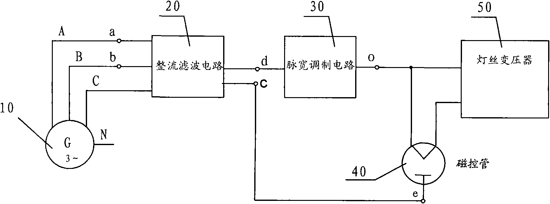
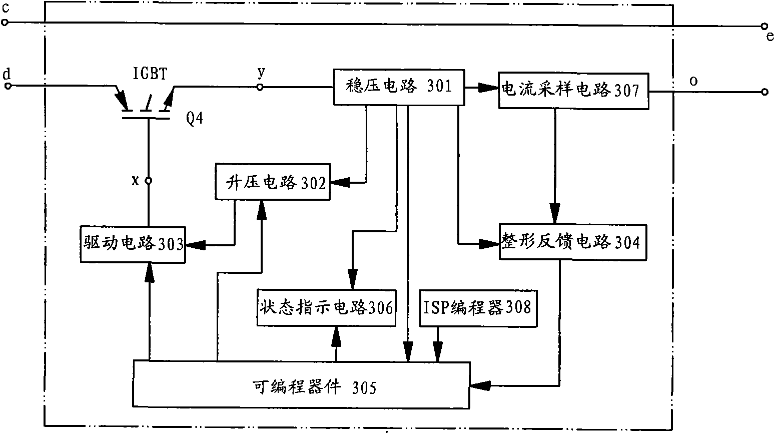
[0024] see Figure 1-Figure 7 , the magnetron drive power supply includes a high-voltage three-phase generator set 10, a rectifier filter circuit 20, a pulse width modulation circuit 30, and more than one magnetron 40, a filament transformer 50, and the high-voltage power generated by the high-voltage three-phase generator set 10. After being rectified and filtered by the filter circuit 20, it is input to the pulse width modulation circuit 30. After the output of the pulse width modulation circuit, it is respectively input to the magnetron 40 and the filament transformer 50. After the filament transformer is transformed, it is input to the magnetron. The final output current is a pulse current with a fixed cycle and a variable duty cycle.

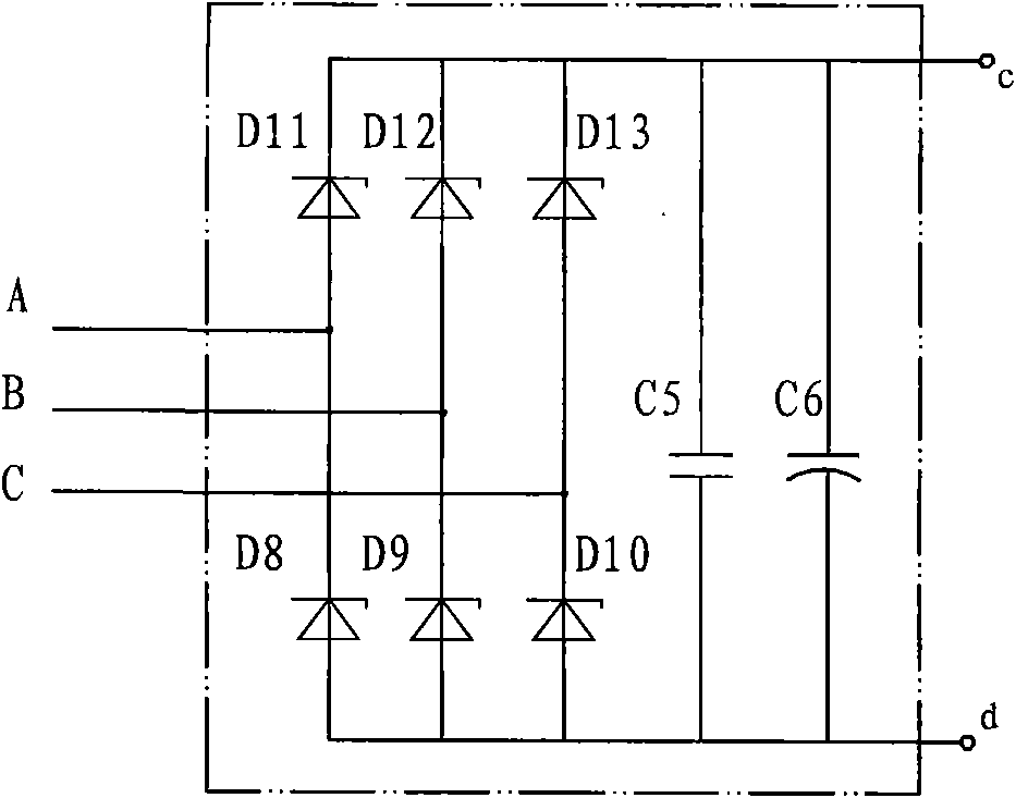
[0025] The rectification filter circuit 20 includes diode D8, diode D9, diode D10, diode D11, diode D12, diode D13,...


PUM


Abstract

The invention relates to a magnetron driving power supply which comprises a high voltage three-phase electric generating set, one or more magnetrons and filament transformators of the same number with the magnetrons; the magnetron driving power supply also comprises a rectification filter circuit and a pulse-width modulation circuit; the high voltage electricity generated by the high voltage three-phase electric generating set is input into the pulse-width modulation circuit through the rectification filter circuit, and then is respectively input into the magnetrons and the filament transformators after being output from the pulse-width modulation circuit; after being processed by voltage transformation of the filament transformators, the high voltage electricity is then input into the magnetrons, and the current output by the pulse-width modulation circuit is pulse current with regular period and changing duty factor. The high voltage three-phase electric generating set is adopted for the magnetron driving power supply, and the rectification filter circuit and the pulse-width modulation circuit are used for replacing a leakage inductance transformer; the pulse-width modulation circuit used for controlling the current of the magnetrons can accurately control the current of the magnetrons, and no radiation fin or other radiating equipment is required to be additionally installed, thus the invention has the advantages of simple circuit structure, reduced volume and weight as well as lowered cost.

Description

technical field [0001] The invention relates to a magnetron driving power supply, in particular to a magnetron driving power supply used in asphalt road surface microwave heating equipment / vehicle. Background technique [0002] Microwave technology is widely used in people's daily production or life, such as microwave sterilization, microwave drying equipment, microwave ovens for food heating, etc. As the microwave generating element magnetron on these microwave equipment, the driving power required by the magnetron should meet the requirements of high voltage and constant current, because these equipment are basically fixed in a specific place for a long time to work, and a machine equipment There are only a small number of magnetron equipment in China. The power supply used is 220V mains or 380V mains or three-phase generators. The high voltage requirements for magnetrons are basically boosted by transformers. To achieve this, as our company discloses a magnetron power su...

Claims


Application Information

Patent Timeline
IPC IPC(8): H05B6/66
CPCY02B40/00
Inventor 张天琦唐相伟黄玉松焦生杰吴济华叶文生
Owner GUANGDONG WITOL VACUUM ELECTRONICS MFR
Learn More