Micro gyro driven by static suspension corona to rotate

An electrostatic levitation and corona technology, applied in the field of micro gyroscopes, can solve the problems of low control accuracy and sensitivity, complex control, complex structure, etc., and achieve the effects of simple structure, improved measurement accuracy, and increased rotational speed.

Inactive Publication Date: 2009-10-21
SHANGHAI JIAO TONG UNIV
View PDF0 Cites 7 Cited by
  • Summary
  • Abstract
  • Description
  • Claims
  • Application Information

AI Technical Summary

Problems solved by technology

[0004] This technology has the following disadvantages. Since the radial recovery control force of the above-mentioned comb electrodes on the rotor is much smaller than the suspension control force on the rotor axial direction, the control accuracy and sensitivity of the rotor radial direction of the gyroscope described in this patent are lower. Lower than the axial; due to the use of variable capacitors to make the rotor rotate at high speed, there must be separate electrodes or land areas equivalent to electrodes on the stator and rotor, and the structure is complex
At the same time, in order to ensure the constant high-speed rotation of the rotor, it is necessary to detect the relative position of the stator and rotor in real time and determine the voltage application sequence of the sub-electrodes. There must be a special constant high-speed detection and control circuit, which is complicated to control.

Method used


Image

  • Micro gyro driven by static suspension corona to rotate
  • Micro gyro driven by static suspension corona to rotate
  • Micro gyro driven by static suspension corona to rotate

Examples


Embodiment Construction

[0018] Embodiments of the present invention are described in detail below in conjunction with the accompanying drawings: this embodiment is implemented on the premise of the technical solution of the present invention, and detailed implementation methods and processes are provided, but the protection scope of the present invention is not limited to the following the embodiment.

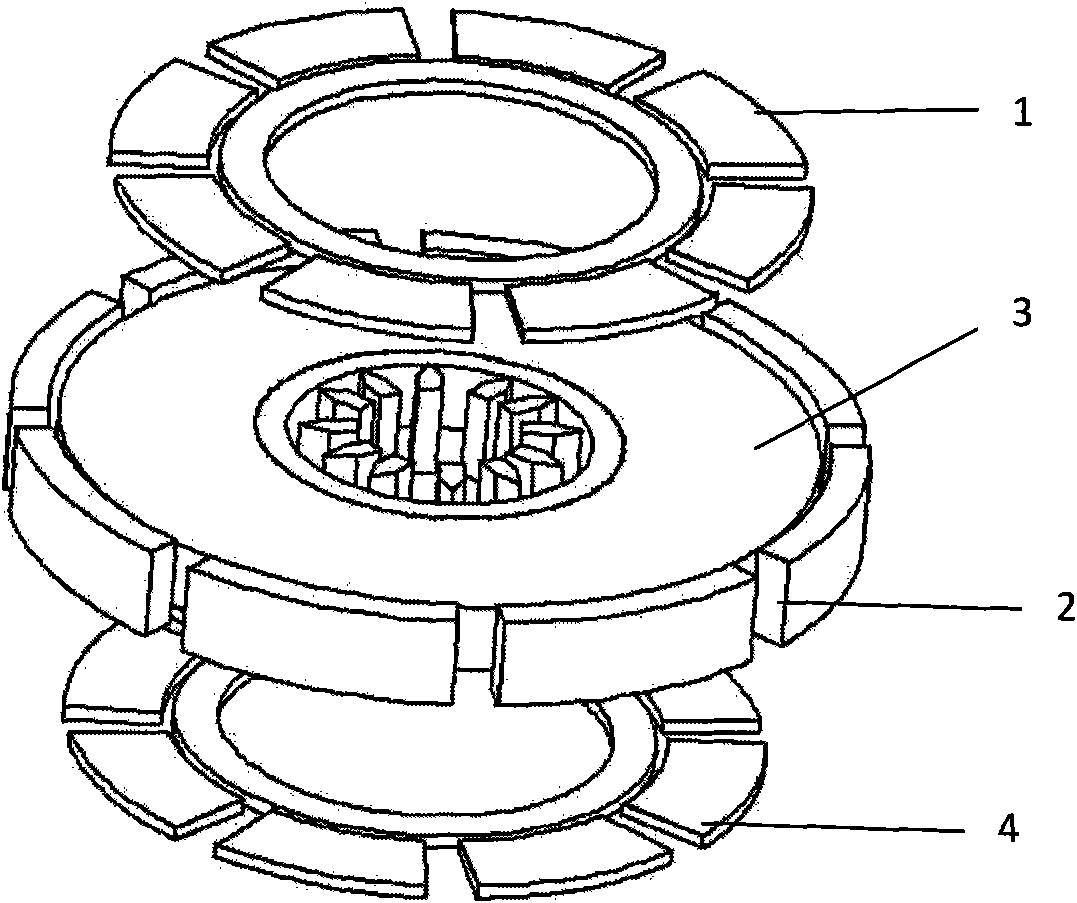
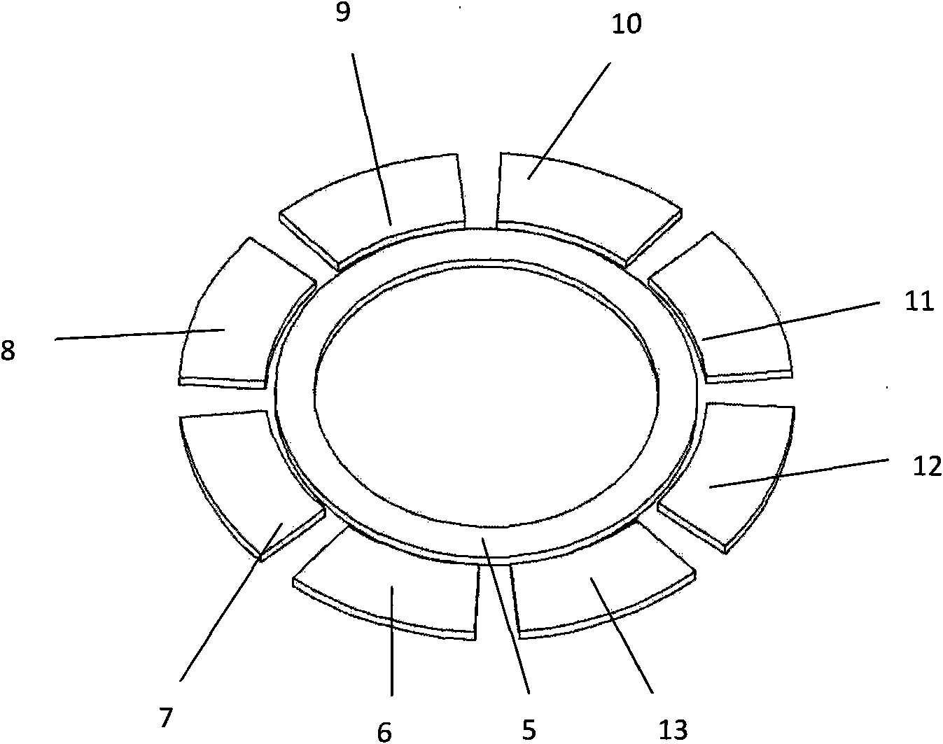
[0019] Such as figure 1 , 2 As shown, this embodiment includes: upper stator 1, lower stator 4, annular rotor 3, peripheral structure 2, upper stator 1, lower stator 4 and peripheral structure 2 are connected to form a cage structure, and annular rotor 3 is placed in this cage middle of the structure. The upper stator 1 includes the first axial detection and suspension electrode 6 of the upper stator, the second axial detection and suspension electrode 7 of the upper stator, the third axial detection and suspension electrode 8 of the upper stator, and the fourth axial detection and suspension electr...


PUM


Abstract

The invention relates to a micro gyro driven by static suspension corona to rotate. The micro gyro comprises upper and lower stators, a micro rotor and a peripheral structure which form a cage structure, and the rotor is arranged in the middle of the cage structure. The stators comprise rotary axial suspension and detection electrodes and public electrodes and are fixedly connected to a substrate; and because of the action of electrostatic force, the micro rotor suspends between the upper and lower stators and has an annular shape, the inside of the micro rotor has tooth-shaped electrodes, while the outside is distributed with a surrounding structure which is radial suspension detection electrodes. The micro gyro has simple structure, provides a corona driving rotary structure, does not need to arrange rotary electrodes on the stators, and can realize the rotation of the rotor at constant high speed without detecting rotating speed. Suspension control of the rotor and position detection can be realized through axial and radial suspension detection electrodes. The micro gyro is made by adopting MEMS micromachining, is easy to implement, and has the characteristics of small size, light weight, low cost, high precision and low power consumption.

Description

technical field [0001] The invention relates to a micro-gyroscope in the field of micro-electromechanical technology (MEMS), in particular to an electrostatic levitation corona-driven rotating micro-gyroscope. Background technique [0002] MEMS devices have the characteristics of miniaturization, low cost, low power consumption, and mass production. In recent years, scholars and engineers from various countries have tried to manufacture suspended rotor MEMS micro gyroscopes. [0003] After searching the literature, it was found that the US patent "acceleration-detecting type gyro and manufacturing method thereof" (patent No. 5920983) mentioned a kind of static electricity of a suspended rotor that can simultaneously measure two-axis angular velocity and three-axis acceleration. The micro-gyroscope adopts glass-silicon-glass bond and structure, the stator is formed by manufacturing electrodes on the glass, and silicon acts as a connection. The rotor is made of monocrystallin...

Claims


Application Information

Patent Timeline
Patent Type & Authority Applications(China)
IPC IPC(8): G01C19/02G01C19/06G01C19/24G01P9/02G01P15/14B81B7/02G01P15/18
Inventor 张卫平刘凯陈文元刘武戴福彦吴校生崔峰
Owner SHANGHAI JIAO TONG UNIV
Why Eureka
Try Eureka