Control circuit of heater control valve

A control circuit and control valve technology, applied in electrical program control, program control in sequence/logic controllers, control systems, etc., can solve problems such as short power supply life, and achieve problems such as difficulty in charging, convenient installation, and convenient management. Effect

Inactive Publication Date: 2009-10-21
SHANDONG JIANZHU UNIV
View PDF0 Cites 6 Cited by
  • Summary
  • Abstract
  • Description
  • Claims
  • Application Information

AI Technical Summary

Problems solved by technology

Its control valve control circuit uses mains electricity without batteries, and the closing of the valve relies on large capacitor discharge, which solves the problem of short power supply life of heat metering devices that has plagued our country for many years

Method used


Image

  • Control circuit of heater control valve

Examples


Embodiment Construction

[0030] Embodiments of the present invention will be described in detail below.

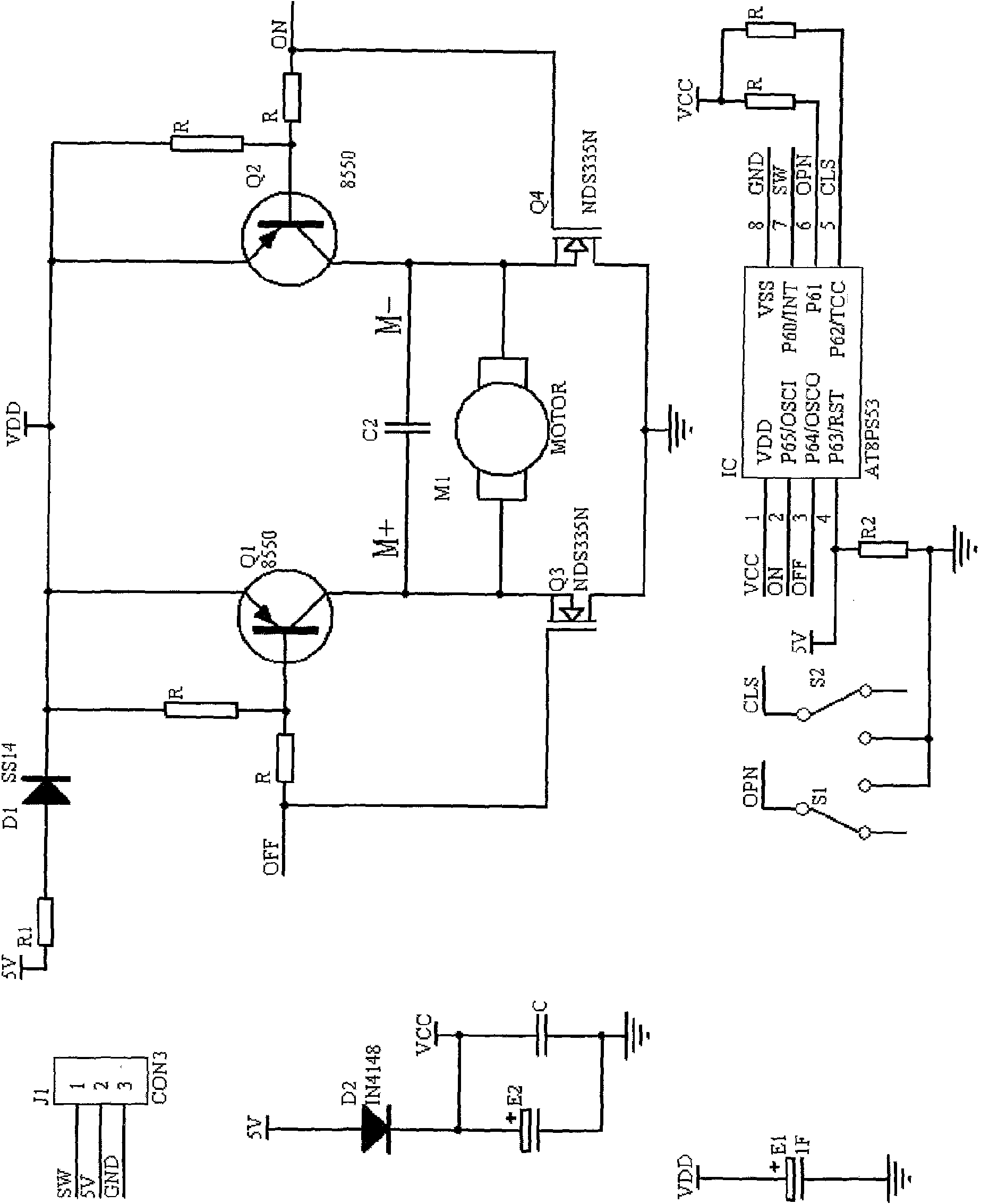
[0031] A heating control valve control circuit, such as figure 1 shown, including:

[0032] A motor M1, used to control the opening and closing of the switch;

[0033] A microprocessor IC, the microprocessor adopts AT series, such as AT8PS53, which is used to receive signals and drive the motor M1 to rotate;

[0034] A supercapacitor E1 stores electric energy and provides electric energy for the motor M1 after power off.

[0035] The P63 pin of the microprocessor is connected to the high potential and grounded through the pull-down resistor R2. The ground wire is also connected with the open limit switch S1 and the close limit switch S2 in parallel. OFF pin, P60 pin is connected to the thermostat control line.

[0036] Between the ON pin and the OFF pin is a motor drive circuit, including a motor M1, two transistors Q1 and Q2 (model 8550), two field effect transistors Q3 and Q4 (model NDS335N)...


PUM


Abstract

A control circuit of a heater control valve comprises a motor (M1) used for controlling on/off of switches, a microprocessor (IC) used for receiving signals and driving the motor (M1) to rotate and a super capacitor (E1) which stores electric energy and provides the electric energy for the motor (M1) after power-down. The control circuit employs the super capacitor instead of common batteries and can freely switch on and switch off the heater valve and set temperature, thereby reducing cost and operating frequency, saving plenty of energy, lowering use cost of users and enjoying high popularization value.

Description

technical field [0001] The invention relates to a control circuit of a heating control valve, which can be applied to a household heating metering system of a new building, or an existing building heating household metering and energy-saving renovation, and is particularly a matching device for a heating intelligent energy-saving metering device. Background technique [0002] my country is a big energy-consuming country, and building energy consumption is a large energy-consuming household in society. Heating energy consumption in northern my country accounts for 25% of local social energy consumption, and heating energy conservation is urgent. my country has taken some measures in terms of heating and energy saving, such as adopting centralized heating and installing heat meters for each household, which has reduced some waste. [0003] However, there are still many problems. Because the traditional heating fee is charged according to the area, users have no enthusiasm for ...

Claims


Application Information

Patent Timeline
Patent Type & Authority Applications(China)
IPC IPC(8): G05B19/04G05D23/19F24D19/10F16K31/04H02P29/00
CPCY02B30/762Y02B30/70
Inventor 宋海洋左利琴宋传增毕洁航孙召宽
Owner SHANDONG JIANZHU UNIV
Why Eureka
Try Eureka