Tundish control flow method of small square billet continuous casting stopper rod and tundish water gap
A small billet continuous casting and stopper technology, which is applied in casting equipment, casting melt containers, manufacturing tools, etc. Quality decline and other problems, to achieve the effect of stable production and increased indirect benefits, reduction of molten steel injection margin, and reduction of steel material consumption
- Summary
- Abstract
- Description
- Claims
- Application Information
AI Technical Summary
Problems solved by technology
Method used
Image

Examples
Embodiment Construction
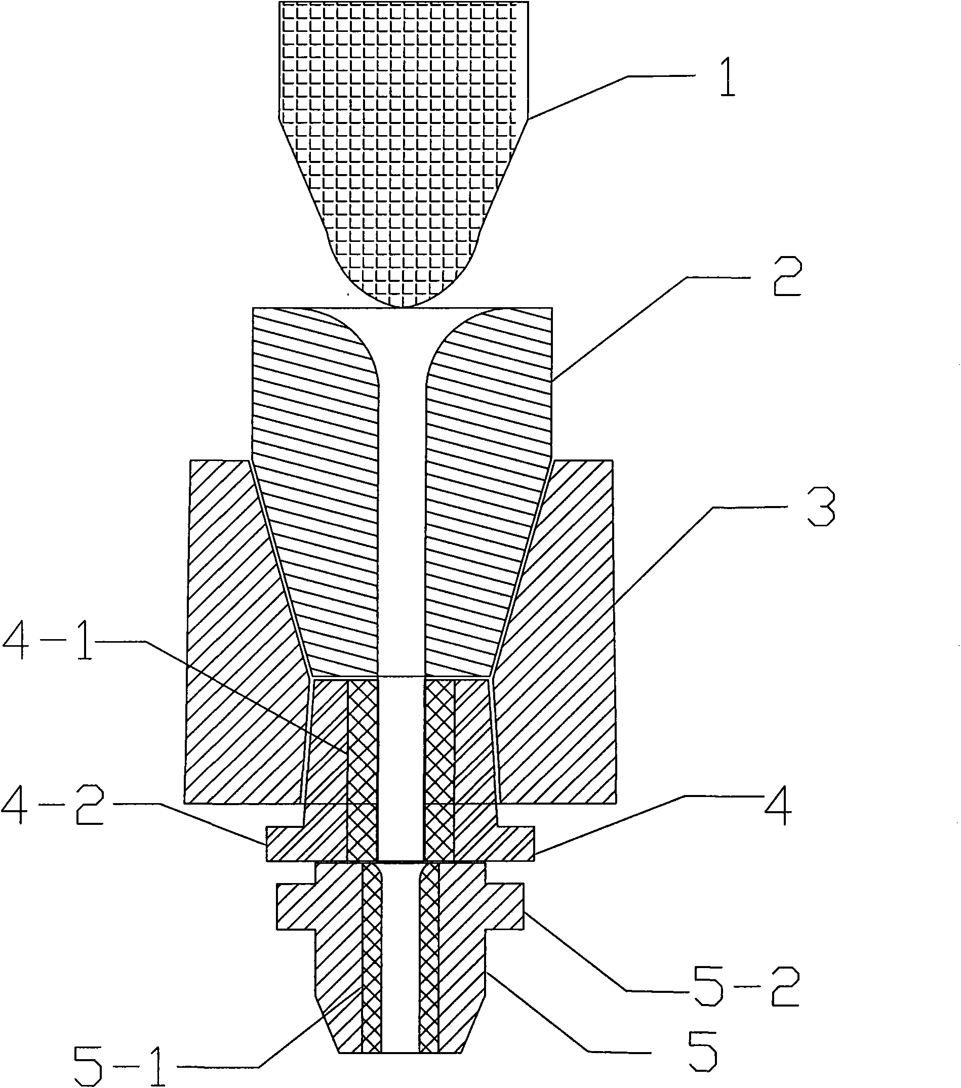
[0023] The billet continuous casting stopper rod tundish flow control method adopts the upper nozzle (stopper nozzle) 2 and the middle nozzle 4 embedded in the zirconium core 4-1 installed from top to bottom in the tundish block 3 from top to bottom And under the tundish seat brick 3, install the tundish nozzle of the lower nozzle 5 closely connected with the middle nozzle 4 and embedded with the zirconium core 5-1; , the lower part and the intermediate nozzle 4 are in the shape of a cone with a small cone angle; the centerlines of the three nozzles coincide, and the outer diameter of the embedded zirconium core 4-1 in the intermediate nozzle 4 is larger than that of the embedded zirconium core 5-1 in the lower nozzle 5 diameter, the inner diameter of the zirconium core 4-1 embedded in the middle nozzle 4 is greater than or equal to the inner diameter of the embedded zirconium core 5-1 in the lower nozzle 5; by adjusting the distance between the stopper rod 1 set on the upper n...
PUM
 Abstract
Description
Claims
Application Information