Pneumatic and hydraulic liquid power retarder controller

A technology of hydraulic retarder and control device, which is applied to hydraulic brakes, brake types, hydraulic resistance brakes, etc., achieves the effects of low cost, simple structure and automatic computer control.

Inactive Publication Date: 2009-10-28
XIANGTAN UNIV
View PDF0 Cites 27 Cited by
  • Summary
  • Abstract
  • Description
  • Claims
  • Application Information

AI Technical Summary

Problems solved by technology

[0003] In order to solve the problem that a medium-high pressure hydraulic pump must be installed when a hydraulic retarder i

Method used


Image

  • Pneumatic and hydraulic liquid power retarder controller
  • Pneumatic and hydraulic liquid power retarder controller

Examples


Example Embodiment

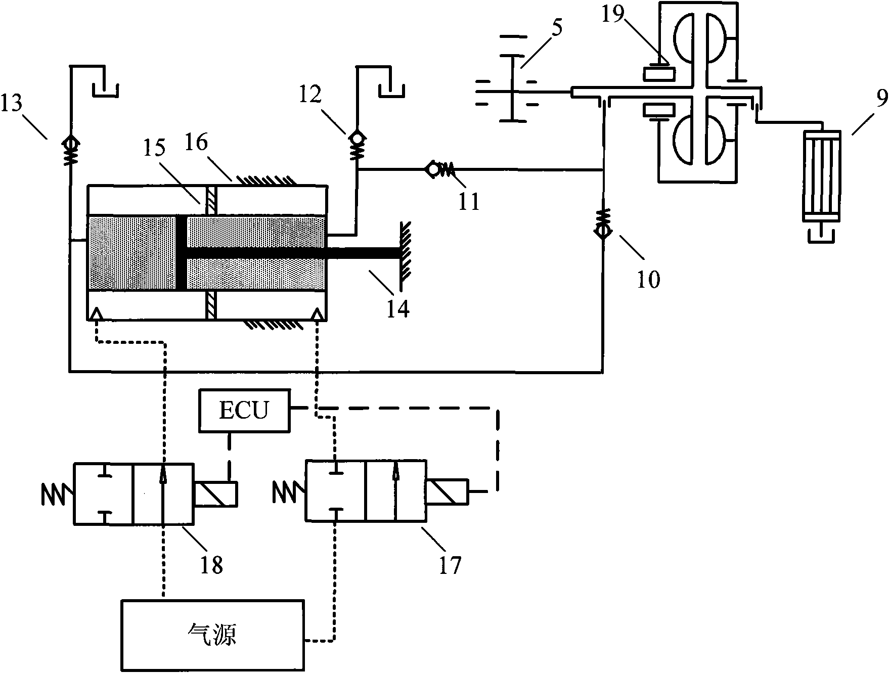
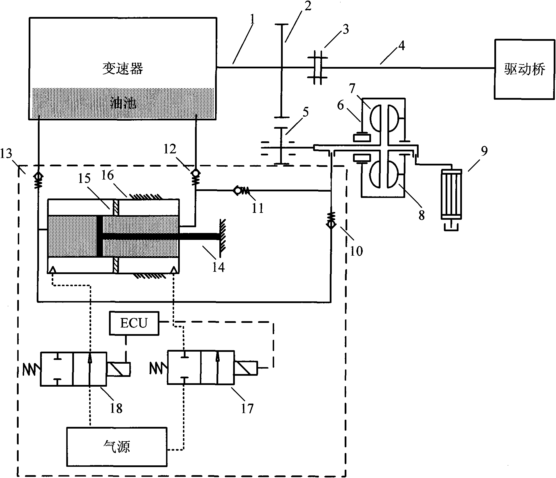
[0010] like figure 1 As shown, a pneumatic-hydraulic hydraulic retarder control device includes a pneumatic-hydraulic converter, and the pneumatic-hydraulic converter is composed of three parts: converter pneumatic cylinder 16, converter pneumatic piston 15 and Converter hydraulic piston 14, the left air chamber of the air pressure-hydraulic converter is connected with the left electromagnetic switch valve 18, and the inlet of the left electromagnetic switch valve 18 is connected with the air source; the right air chamber of the air pressure-hydraulic converter is connected with the right electromagnetic switch valve 17, and the right The inlet of the electromagnetic switch valve 17 is connected to the air source, and the ECU is connected between the working position of the left electromagnetic switch valve 18 and the working position of the right electromagnetic switch valve 17; The oil tank of the transmission is connected with the working oil chamber of the hydraulic retard...


PUM


Abstract

The invention discloses a pneumatic and hydraulic liquid power retarder controller, comprising a pneumatic-hydraulic convertor consisting of a converter pneumatic cylinder, a converter pneumatic piston and a converter hydraulic piston, wherein a left air cavity of the pneumatic-hydraulic convertor is connected with a left electromagnetic switching valve, an inlet of which is connected with an air source; a right air cavity of the pneumatic-hydraulic convertor is connected with a right electromagnetic switching valve, an inlet of which is connected with an air source, and an ECU is connected between the working position of the left electromagnetic switching valve and the working position of the right electromagnetic switching valve; a left oil cavity of the pneumatic-hydraulic convertor is connected with a transmission oil pool through a left oil pool one-way valve and connected with a working oil pool of a hydraulic retarder through a right retarder one-way valve; a right oil cavity of the pneumatic-hydraulic convertor is connected with the converter oil pool through a right oil pool one-way valve; a bypass one-way valve is connected between the front end of the right oil pool one-way valve and the rear end of the right retarder one-way valve; and a hydraulic retarder driving gear is arranged on the pump wheel shaft of the hydraulic retarder, a turbine of the hydraulic retarder is fixed on the housing and an oil outlet thereof is connected with a heat exchanger. The invention has the beneficial effects as follows: 1. the existing air sources of the vehicles can accomplish the transportation of medium to save the special intermediate and high pressure hydraulic pumps; 2. the electromagnetic switching valves are used instead of the conventional electro-hydraulic proportional valves to assist the achievement of automatic control of computer; and 3. simple structure and low cost are provided.

Description

technical field [0001] The invention relates to a hydraulic retarder control device for a vehicle, in particular to a hydraulic retarder control device for a vehicle with only an air source but no hydraulic source. Background technique [0002] When the vehicle goes downhill, it is often necessary to use the service brake continuously or frequently, resulting in severe wear of the brake drum and brake pads, and even cracking of the brake drum and burning of the brake pads due to heat, which not only reduces the service life of the service brake, Increased operating costs, serious threats to driving safety. Installing a retarder can make a vehicle with a large mass decelerate smoothly without consuming the braking system, which is an effective way to solve the above problems, especially medium and large vehicles are basically equipped with this auxiliary braking device. At present, the commonly used retarders can be divided into two types in terms of structure: electromagnet...

Claims


Application Information

Patent Timeline
IPC IPC(8): F16D57/00B60T10/02
Inventor 刘金刚谭援强杨世平张高峰
Owner XIANGTAN UNIV
Why Eureka
Try Eureka