Unlock instant, AI-driven research and patent intelligence for your innovation.
Production method of semi-conductive buffer water-blocking band
What is Al technical title?
Al technical title is built by PatSnap Al team. It summarizes the technical point description of the patent document.
A production method and technology of water-blocking tape, applied in the direction of conductor/cable insulation, conductor, circuit, etc., can solve problems such as unsatisfactory electrical conductivity, unadvanced manufacturing technology, and increased volume resistance, so as to meet the requirements of normal work Temperature, good water blocking effect, small surface resistance effect
Active Publication Date: 2011-01-19
YANG ZHOU TENGFEI ELECTRIC CABLE & APPLIANCE MATERIALS CO LTD
View PDF0 Cites 0 Cited by
Summary
Abstract
Description
Claims
Application Information
AI Technical Summary
This helps you quickly interpret patents by identifying the three key elements:
Problems solved by technology
Method used
Benefits of technology
Problems solved by technology
[0002] Semi-conductive buffer water-blocking tape is commonly used in the high-voltage cross-linked power cable industry. It can produce semi-conductive shielding and buffer the electric field. At the same time, it requires good water absorption capacity to protect the cable core from moisture. , but the current semi-conductive buffer water-blocking tape has unsatisfactory electrical conductivity due to its unadvanced manufacturing process, and the interior of the base fabric material cannot fully absorb the electrolyte, which increases the volume resistance and affects its electrical conductivity.
Method used
Image
Click on the blue label to locate the original text in one second.
Reading with bidirectional positioning of images and text.
Examples
Embodiment 1
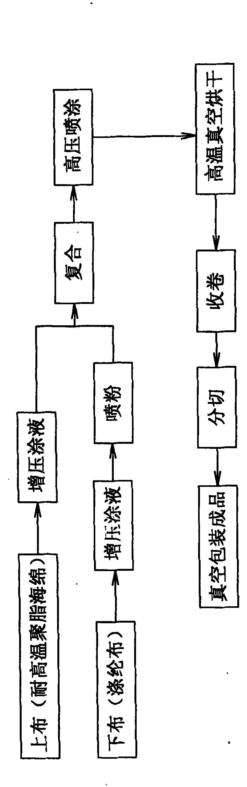
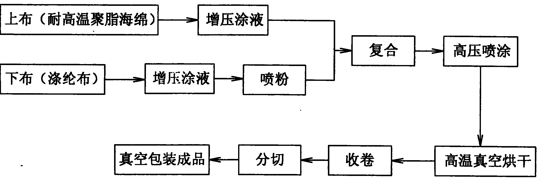
[0021] The present invention produces by following process route:
[0022] (1) With conductive liquid: the mass percentage of each component in the conductive liquid is as follows: the content of carbon is 20%, acrylic acid is 12%, leveling is 3%, dispersant is 1.5%, and the rest is water. After the parts are mixed evenly, they are placed in a mixer and stirred at a stirring speed of 1200 rpm.
[0023] (2) Pressurized coating solution: impregnate the polyester cloth with conductive liquid in the pressurized rubber tank, and at the same time, the pressure in the pressurized rubber tank is greater than 4 times the atmospheric pressure, so that the conductive liquid is impregnated into the polyester cloth, and the polyester cloth is pressurized The running speed in the glue tank is 10-15 m / min.
[0024] (3) Dust spraying: Let the impregnated polyester cloth be evenly sprayed with a certain amount of super absorbent resin on its surface, and the powder spraying amount should be c...
Embodiment 2
[0030] The present invention produces by following process route:
[0031] (1) With conductive liquid: the mass percentage of each component in the conductive liquid is: the content of carbon is 30%, acrylic acid is at 10%, flatness is at 2%, dispersant is at 1%, and the rest is water. After the parts are mixed evenly, they are placed in a mixer and stirred at a stirring speed of 1000 rpm.
[0032] (2) Pressurized coating solution: impregnate the polyester cloth with conductive liquid in the pressurized rubber tank, and at the same time, the pressure in the pressurized rubber tank is greater than 4 times the atmospheric pressure, so that the conductive liquid is impregnated into the polyester cloth, and the polyester cloth is pressurized The running speed in the glue tank is 10-15 m / min.
[0033] (3) Dust spraying: Let the impregnated polyester cloth be evenly sprayed with a certain amount of super absorbent resin on its surface, and the powder spraying amount should be contr...
PUM
Abstract
The invention relates to a production method of a water-blocking band, in particular to a production method of a semi-conductive buffer water-blocking band. The production method comprises the following steps: firstly, supercharging and soaking a high-temperature resistant polyester sponge and terylene cloth in conductive liquid, spraying high water-absorbent resin on the terylene cloth and compounding the high-temperature resistant polyester sponge and the terylene cloth; then, spraying the conductive liquid with a high-pressure spray gun and drying the high-temperature resistant polyester sponge and the terylene cloth which are compounded in vacuum at a high temperature; and finally, coiling, cutting and packaging the high-temperature resistant polyester sponge and the terylene cloth which are compounded in vacuum to be a finished semi-conductive buffer water-blocking band . Proved by detection, the semi-conductive buffer water-blocking band has the advantages of high intensity, thinness, rapid swelling in water, high water absorption, good water-blocking effect, high-temperature environment influence resistance, small surface resistance, low volume electric resistivity, EuropeanUnion environmental protection accordance, and the like, can satisfy the water blocking and the electric field shielding among parts of power cables, and the like, maintains the safe use of the cables, can generate the semi-conductive shielding action so as to buffer an electric field, can be lined at the inner side of a metal protective sleeve to buffer the friction between the inner protectivesleeve and the metal protective sleeve and can satisfy the normal working temperature of the cables.
Description
technical field [0001] The invention relates to a production method of a water-blocking tape, in particular to a production method of a semi-conductive buffer water-blocking tape suitable for power cables. Background technique [0002] Semi-conductive buffer water-blocking tape is commonly used in the high-voltage cross-linked power cable industry. It can produce semi-conductive shielding and buffer the electric field. At the same time, it requires good water absorption capacity to protect the cable core from moisture. , but the current semi-conductive buffer water-blocking tape has unsatisfactory electrical conductivity due to its unadvanced manufacturing process, and the current base material cannot fully soak and absorb the electrolyte, which increases the volume resistance and affects its electrical conductivity. Contents of the invention [0003] The purpose of the present invention is to provide a production method of the semi-conductive buffer water-blocking tape wh...
Claims
Application Information
Patent Timeline
Application Date:The date an application was filed.
Publication Date:The date a patent or application was officially published.
First Publication Date:The earliest publication date of a patent with the same application number.
Issue Date:Publication date of the patent grant document.
PCT Entry Date:The Entry date of PCT National Phase.
Estimated Expiry Date:The statutory expiry date of a patent right according to the Patent Law, and it is the longest term of protection that the patent right can achieve without the termination of the patent right due to other reasons(Term extension factor has been taken into account ).
Invalid Date:Actual expiry date is based on effective date or publication date of legal transaction data of invalid patent.

