
Highly conductive composites

a composite material and high electrical conductivity technology, applied in the direction of non-metal conductors, energy-based chemical/physical/physicochemical processes, coatings, etc., can solve the problems of increasing the power to drive the more resistive circuit, significantly reducing the bonding strength of the composite material, and high electrical conductivity often requires high filler loading, so as to achieve a significantly reduced percolation threshold and low percolation threshold

Inactive Publication Date: 2013-01-01
PIXELLIGENT TECH LLC
View PDF3 Cites 4 Cited by
  • Summary
  • Abstract
  • Description
  • Claims
  • Application Information

AI Technical Summary

Benefits of technology

This approach enhances thermal and electrical conductivity while maintaining mechanical strength and adhesion, allowing for efficient heat dissipation, reduced processing temperatures, and improved performance in various applications with reduced filler content.

Problems solved by technology

Over the past decade, as on chip interconnect dimensions have been reduced, power to drive the more resistive circuits has become more and more problematic.
Using traditional conductive fillers to effectively increase the thermal conductivity of the composite typically requires high levels of loading, which significantly decrease the bonding strength of the composites.
High electrical conductivity often requires high filler loading.
However, adhesion strength and / or mechanical properties often suffer as a result of high filler loading.
However, ITO, as well as FTO, is expensive due to the short supply of indium.
Moreover, ITO is far from ideal for many of the fastest growing application sectors in which transparent conductors are used.
For instance, the inherit brittleness of ITO constrains its application in touch screen displays since it cracks easily.
Other transparent electrical conductive film, such as transparent carbon nanotube sheet, while is strong and flexible, is more costly and has not fully entered industrial applications.
Rapid discharge of the static charge build up can generate a large electric current or an electrical spark, which may be extremely harmful to electronic devices, around flammable and ignitable materials, and in space exploration.
EMI exists when an electromagnetic disturbance induces undesirable voltages or currents that adversely influence the performance of electronics or electrical devices.
Electromagnetic interference works in different ways to degrade the performance of an electronic device.
The most common form of interference is the electrical current generated in an electrical circuit, when it is hit by an electromagnetic disturbance.
Depending upon the magnitude of the electrical disturbance, the induced electrical current can either corrupt a low level signal or override and eventually destroy the circuit.
However, in an application such as an electric-thermal heating unit, materials with high electrical conductivity and low thermal conductivity are needed.

Method used


Image

  • Highly conductive composites
  • Highly conductive composites
  • Highly conductive composites

Examples


Embodiment Construction

Multiple Component System

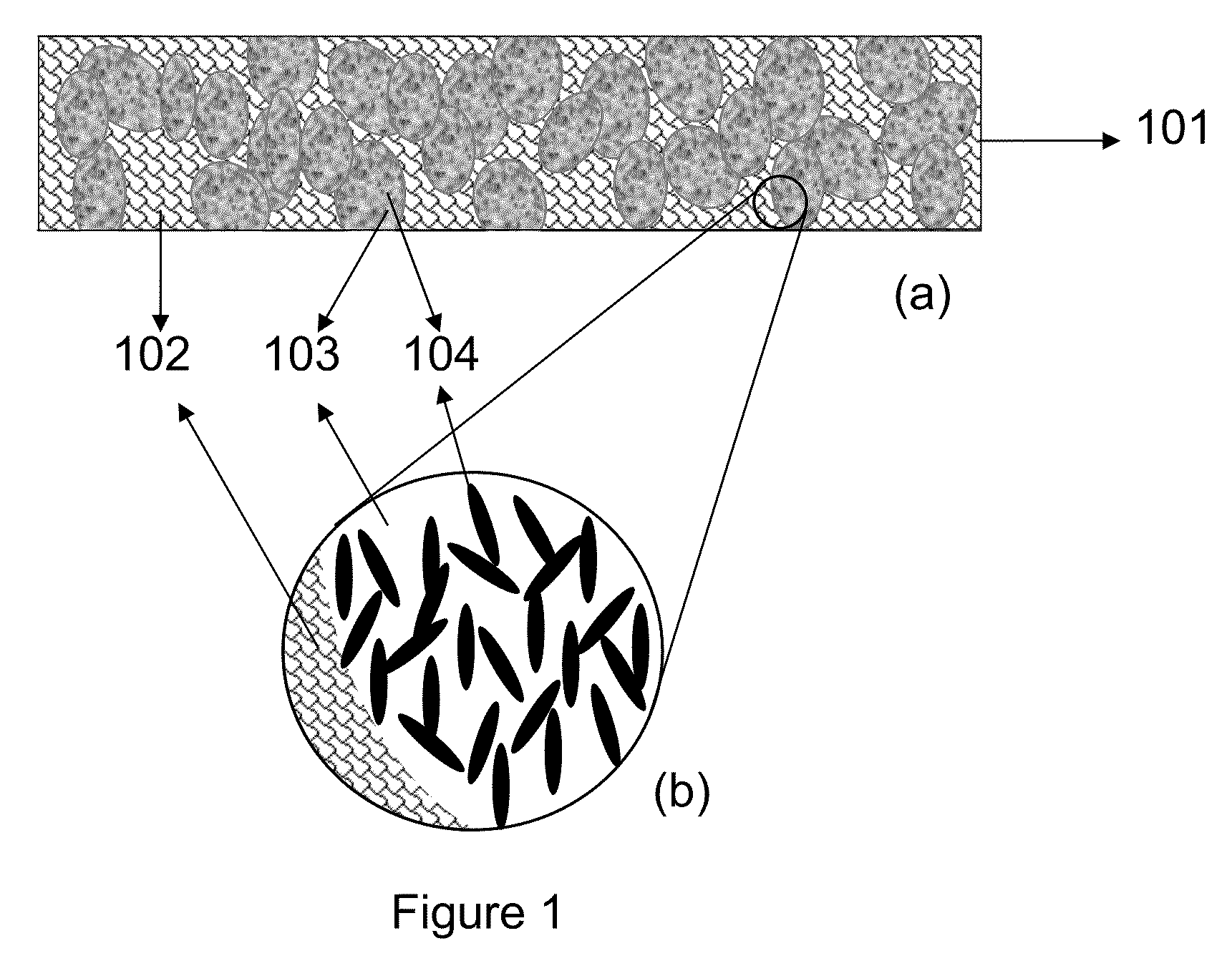
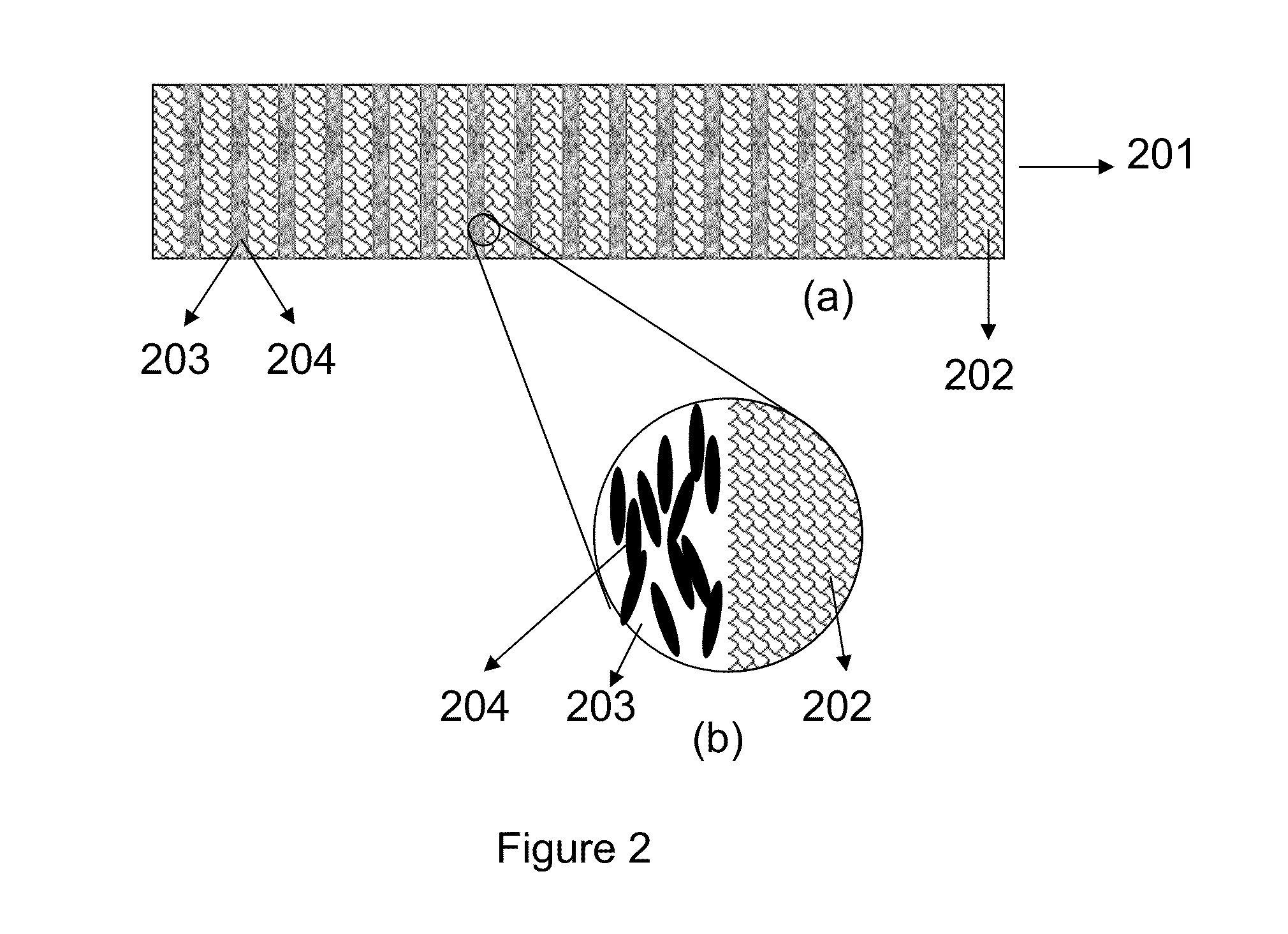
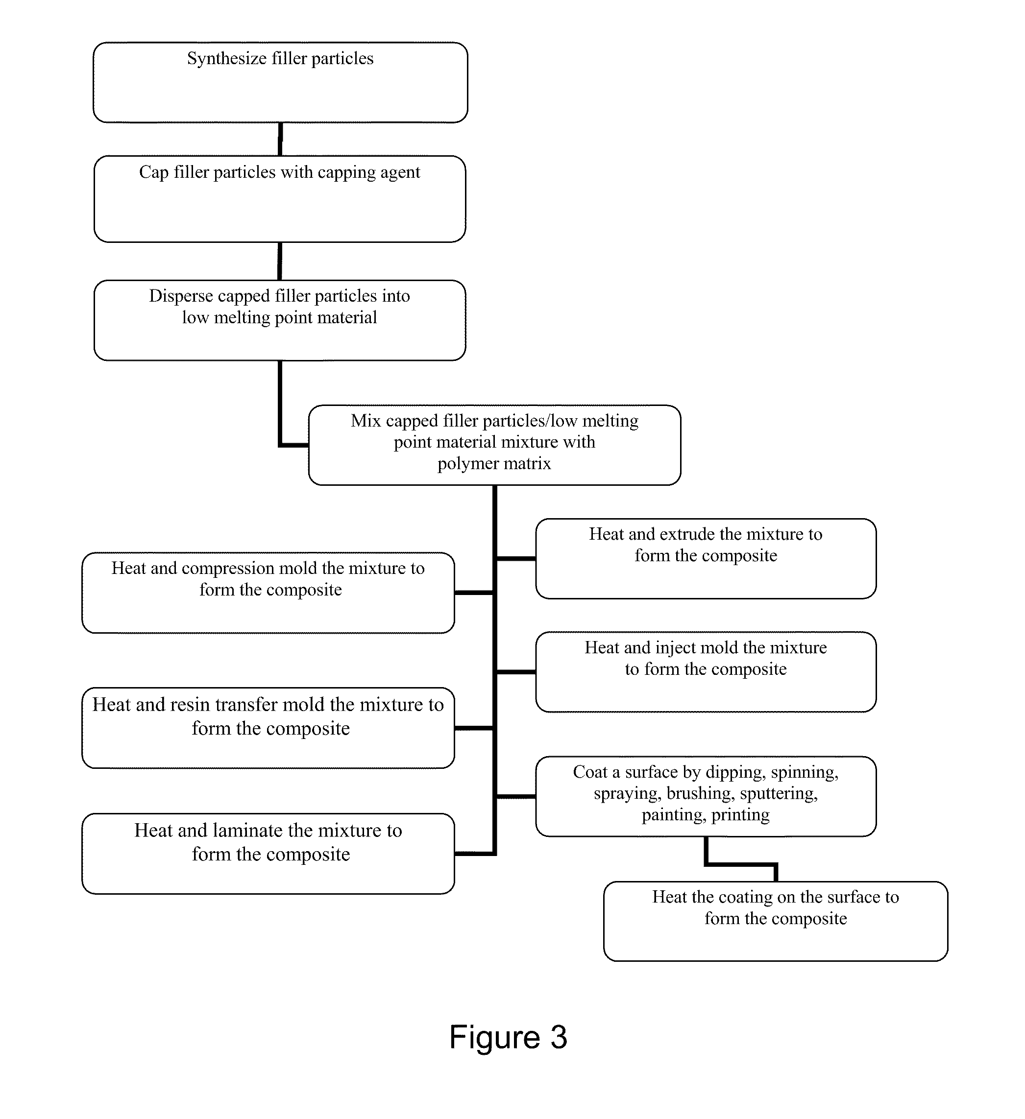
[0045]One exemplary non-limiting illustrative embodiment provides a two phase polymer material with at least one type, shape or phase of filler in at least one polymer phase. One phase of polymer is the matrix material (Component A) and the other phase of the polymer is a low melting material (Component B) or low softening temperature material. The matrix material can be either a thermosetting polymer, or a thermoplastic polymer, or a rubbery material which provides the required mechanical properties and necessary binding properties of the composites. The segregated second phase material could be, but not limited to, a polymeric material with relatively low melting point depending on the desired working temperature (melting point lower than the working temperature). This segregated domain flows above its melting temperature to fill up any air gaps at the interface between the composite and the substrate to ensure the maximum contact area. The filler (Compone...


PUM

PropertyMeasurementUnit
temperatureaaaaaaaaaa
domain sizeaaaaaaaaaa
thermal conductivitiesaaaaaaaaaa

Abstract

Domain segregation of polymer blends or block copolymers in the presence of thermal conducting high aspect ratio nanocrystals leads to preferential placement of conductive filler either inside one domain, which promote the self-assembly of a thermal and / or electrical conducting pathway composed of high aspect ratio filler. The self-assembly of such thermal and / or electrical conducting pathway effectively enhances the thermal and / or electrical conductivity of the composite with significantly less amount of filler.

Description

CROSS-REFERENCES TO RELATED APPLICATIONS[0001]This application claims the benefit of priority from provisional application No. 61 / 241,273 filed Sep. 10, 2009, incorporated herein by reference.FIELD[0002]The technology herein relates to conductive composite materials, and more particularly to multi-component domain segregated materials.BACKGROUND AND SUMMARYPercolation and Nanocomposites[0003]In a conductive network, the conductivity can be guided by percolation theory. Mathematically, percolation can be described as the following: in an infinite network, there is a path of connected points of infinite length “through” the network. With increasing population of the conducting points, there exists a critical number above which at least one conducting pathway forms within the network. The critical point is called percolation threshold which is a particle-size and geometry-dependent parameter for composites. Generally, smaller particles allow for a lower percolation threshold, due to th...

Claims


Application Information

Patent Timeline
Patent Type & Authority Patents(United States)
IPC IPC(8): C08K3/10H01R43/00B29C48/00B29C48/05B29C48/06
CPCH01B1/22B01J19/08B05D3/12B05D5/00B05D3/02B29C47/00B29C43/00B29C45/00C09K5/00H01B1/12H05K3/22B29C47/0014B29C47/0016H01B1/24Y10T29/49117B29C48/00B29C48/05B29C48/06
Inventor XU, WEIXU, JUNGONEN-WILLIAMS, ZEHRA SERPILCOOPER, GREGORY D.
Owner PIXELLIGENT TECH LLC
Learn More