Check patentability & draft patents in minutes with Patsnap Eureka AI!

Worm-wheel stroke internal combustion engine

An internal combustion engine and turbine technology, applied in combustion engines, engine components, machines/engines, etc., can solve the problems of accelerating component wear, affecting engine service life, and high energy consumption, improving energy conversion rate, avoiding high-frequency jitter, The effect of improving the service life

Inactive Publication Date: 2009-11-04
陈名碧
View PDF0 Cites 2 Cited by
  • Summary
  • Abstract
  • Description
  • Claims
  • Application Information

AI Technical Summary

Problems solved by technology

[0002] Although there are many types of engines currently in use, the crank stroke engine is still the most widely used and the most common. This machine has high energy consumption, and the energy conversion rate is only about 30%. This is because the piston moves to the bottom dead center. Exhaust. At this time, the air pressure in the cylinder is still relatively high, and the temperature is as high as 300-400°C. Nearly 50% of the energy and fuel are discharged as exhaust gas, which not only affects the conversion of energy into effective work, but also seriously affects the environment.
At the same time, the ratio of the crankshaft stroke engine power to the body volume is small, that is, the crankshaft stroke engine with the same volume has much smaller power and much heavier weight than the fuel turbine engine with the same volume. Vibration up and down affects the smooth operation of the engine, accelerates the wear of various components, and affects the service life of the engine
Although the turbojet engine and turbofire engine currently in use have high power, high power to volume ratio, and relatively stable operation, their energy conversion rate is low, only about 20%.
Therefore how to make full use of the advantages of the above two kinds of engines and overcome their shortcomings has become a research topic that people pay close attention to. So far, no new engine combining the above two has been seen.

Method used


Image

  • Worm-wheel stroke internal combustion engine
  • Worm-wheel stroke internal combustion engine
  • Worm-wheel stroke internal combustion engine

Examples


Embodiment Construction

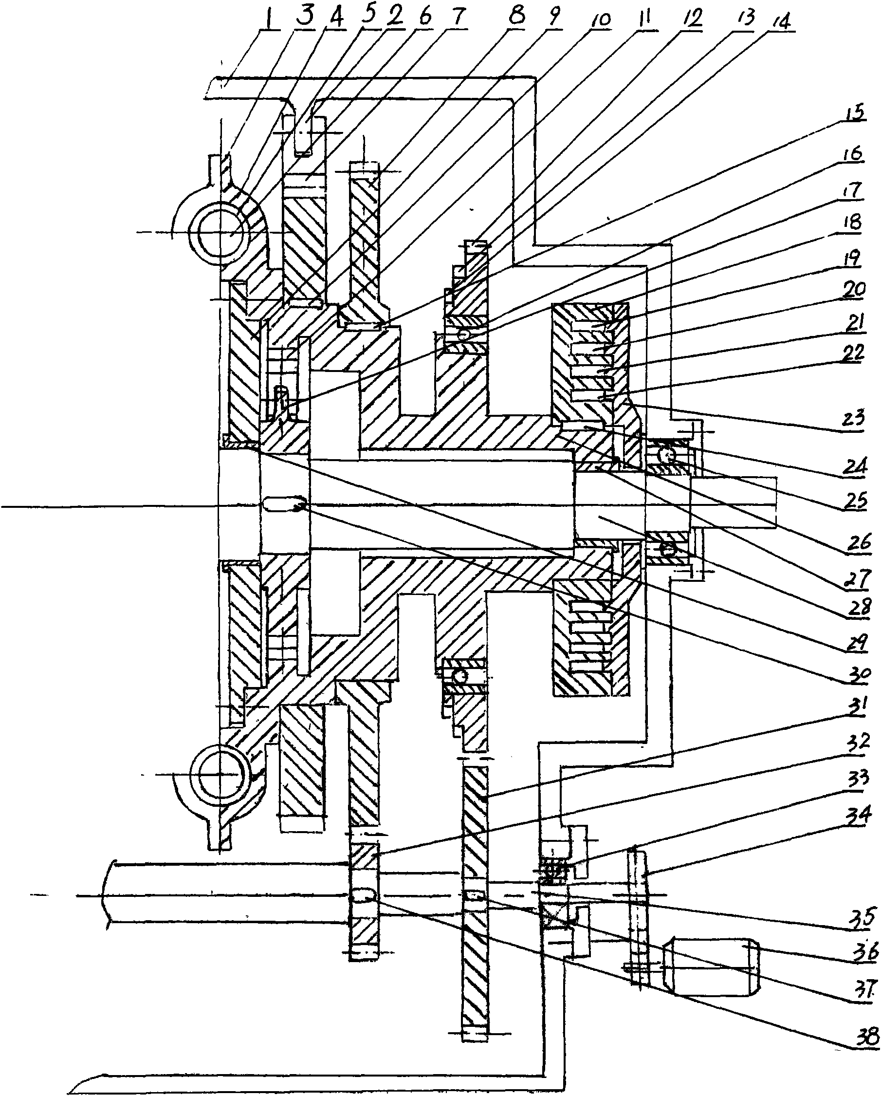
[0012] like Figure 1 to Figure 3 As shown, the present invention includes body shell 1, cylinder block 4, 5, cylinder head 6, transmission component connecting member and oil, water, gas supply pipe and exhaust pipe, is characterized in that two symmetrical semi- Body, two half bodies are connected through the main shaft 28, and the underside of the half body is provided with an auxiliary shaft 35 parallel to the main shaft. On the auxiliary shaft, a middle gear 31 meshing with the main shaft gear 12 and an arc gear 31 are bonded by keys 37 and 38. The pinion 32 meshed with the shaped ratchet gear 8, the so-called arc ratchet gear is provided with tooth segments in sections, and the number of tooth segments depends on the number of cylinder heads. For example, four cylinder heads are four sections, and eight cylinder heads are eight sections. Sections, and so on, the main and auxiliary shafts are socketed with the body shell through bearings 25, 33, and the outer end of the a...


PUM


Abstract

The invention discloses a worm-wheel stroke internal combustion engine, comprising a engine body shell (1), cylinder bodies (4) and (5), a cylinder head (6), a transmission component, a connecting component, and oil, water and gas supplying and gas discharging pipelines, wherein the engine body shell therein is provided with two symmetrical half engine bodies which are connected with each other by a main shaft (28). The lower sides of the half engine bodies are provided with auxiliary shafts (35) parallel with the main shaft. Each auxiliary shaft thereon is provided, in a bonding manner, with an intermediate gear (30) engaged with a main shaft rack wheel (12) and a pinion (32) engaged with an arched ratchet (8). The main and auxiliary shafts (25) and (33) are sleeved with the engine body shell. The outer end of the auxiliary shaft is connected with a starting motor (36). The invention increases the energy transformation rate by 1 time to 60% compared with prior crank shaft engine, reduces environmental pollution, runs stably, improves the service life of the engine, and increase the ratio of power to engine body volume.

Description

technical field [0001] The invention relates to an engine, especially a turbo stroke internal combustion engine. Background technique [0002] Although there are many types of engines currently in use, the crank stroke engine is still the most widely used and the most common. This machine has high energy consumption, and the energy conversion rate is only about 30%. This is because the piston moves to the bottom dead center. Exhaust, at this time the air pressure in the cylinder is still high, the temperature is as high as 300-400°C, and nearly 50% of the energy and fuel are discharged as exhaust gas, which not only affects the conversion of energy into effective work, but also seriously affects the environment. At the same time, the ratio of the crankshaft stroke engine power to the body volume is small, that is, the crankshaft stroke engine with the same volume has much smaller power and much heavier weight than the fuel turbine engine with the same volume. Vibration up a...

Claims


Application Information

Patent Timeline
Patent Type & Authority Applications(China)
IPC IPC(8): F02B39/04F02B33/40
Inventor 陈名碧
Owner 陈名碧
Features
  • R&D
  • Intellectual Property
  • Life Sciences
  • Materials
  • Tech Scout
  • Unparalleled Data Quality
  • Higher Quality Content
  • 60% Fewer Hallucinations
Learn More