
Fiber grating monitoring method for curing residual strain of composite materials

A technology of composite materials and optical fiber gratings, applied in the field of material science, can solve the problems of being unable to withstand high temperature curing of composite materials, being easily affected by electric fields, and structural damage, and achieving stable and reliable measurement values, on-line monitoring, and good repeatability

Inactive Publication Date: 2009-11-04
SHENYANG INST OF AERONAUTICAL ENG +1
View PDF0 Cites 29 Cited by
  • Summary
  • Abstract
  • Description
  • Claims
  • Application Information

AI Technical Summary

Problems solved by technology

[0003] The measurement method of curing residual strain usually adopts delamination method and drilling method, but these methods can only be limited to a specific area of ​​the structure, and will cause damage to the original structure
Non-destructive testing methods such as dielectric analysis and electronic strain gauges measure the curing residual strain, but the shrinkage stress generated by the embedded sensor during the curing of the composite material will affect the performance of the structure. Influenced by the electric field, at the same time, it cannot withstand the high temperature of composite material curing

Method used


Image

  • Fiber grating monitoring method for curing residual strain of composite materials
  • Fiber grating monitoring method for curing residual strain of composite materials
  • Fiber grating monitoring method for curing residual strain of composite materials

Examples


Embodiment Construction

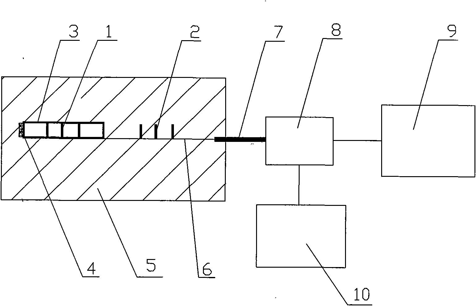
[0014] exist figure 1 Among them, symbol 1 stands for grating temperature sensor; symbol 2 stands for grating temperature strain sensor; symbol 3 stands for glass capillary; symbol 4 stands for silicone rubber package; symbol 5 stands for composite material; symbol 6 stands for optical fiber; symbol 7 stands for quartz sheath; symbol 8 Represents a coupler; symbol 9 represents a grating demodulator; symbol 10 represents a broadband light source.

[0015] Such as figure 1 Shown: A fiber grating monitoring method for curing residual strain of composite materials, the specific operation is as follows:

[0016] (1) The optical fiber 6 can be an optical fiber with a standard diameter of 125 μm, or an optical fiber with a small core diameter of 40 μm, and the grating temperature sensor 1 and the grating temperature strain sensor 2 are written on the optical fiber 6, wherein the grating temperature sensor 1 located at the end of the optical fiber 6 It is made by encapsulating a bar...


PUM

PropertyMeasurementUnit
Lengthaaaaaaaaaa
Center wavelengthaaaaaaaaaa

Abstract

The invention provides a fiber grating monitoring method for the curing residual strain of composite materials. The method comprises the following steps: (1) manufacturing a sensor string comprising grating temperature sensors and grating temperature strain sensors; (2) embedding fiber grating sensors in to-be-monitored parts of a composite material in the process of layering the composite material; (3) reasonably selecting a molding process for the composite material, such as hot-pressing reactor, compression molding and the like; (4) cooling the composite material to room temperature after curing molding is performed and using a grating demodulation instrument to monitor the wavelength value of the highest reflection peak of a reflection spectrum of a fiber grating; and (5) utilizing epsilon=1 / k epsilon((delta lambda B1 / lambda B1)-(Delta lambda B2 / lambda B2)) to calculate the curing residual strain of the composite material. The method can realize the measurement of the residual strain of key parts of the structure of the composite material on the premise of not destroying the structure, and has the advantages of stable reliable measured values and good repeatability; in addition, the embedded grating can continue to play a role in monitoring the structure health of the composite material. The method organically combines the digital manufacturing and the health monitoring of the composite material, thereby realizing the on-line monitoring for the manufacturing process of the composite material.

Description

technical field [0001] The invention relates to a monitoring method, in particular to a fiber grating monitoring method for curing residual strain of a composite material, and belongs to the field of material science. Background technique [0002] Composite materials have excellent mechanical properties, but the differences in physical and mechanical properties and thermal expansion coefficient mismatch of the component materials often lead to the generation of residual stress / strain during the molding process. This curing residual stress will affect the dimensional stability of the composite material, and at the same time have a non-negligible impact on the damage propagation of the composite structure during service. Therefore, monitoring and controlling the generation of curing residual strain is very critical to improve the reliability of composite materials. [0003] The measurement method of curing residual strain usually adopts delamination method and drilling method...

Claims


Application Information

Patent Timeline
IPC IPC(8): G01N21/84G01B11/16
Inventor 卢少微陈平王柏臣高禹陆春李伟于祺
Owner SHENYANG INST OF AERONAUTICAL ENG
Learn More