

System for monitoring contact temperature of high-voltage switch cabinet on line
A high-voltage switchgear and monitoring system technology, applied to thermometers, signal transmission systems, and parts of thermometers, etc., can solve problems such as unreliable work, achieve high reliability, broaden the application range, and strong anti-interference ability.
- Summary
- Abstract
- Description
- Claims
- Application Information
AI Technical Summary
Problems solved by technology
Method used
Image

Examples
Embodiment Construction
[0025] The present invention will be described in detail below in conjunction with the accompanying drawings and specific embodiments.
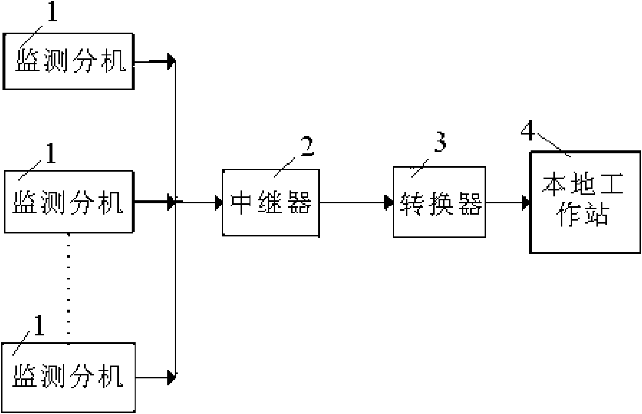
[0026] The structure of an embodiment of the monitoring system of the present invention, such as figure 1 As shown, it includes a repeater 2, a converter 3 and a local workstation 4 connected in sequence. The repeater 2 is also connected to a plurality of monitoring extensions 1. The repeater 2 uses an RS-485 repeater, and the converter 3 Using RS-485 converter.
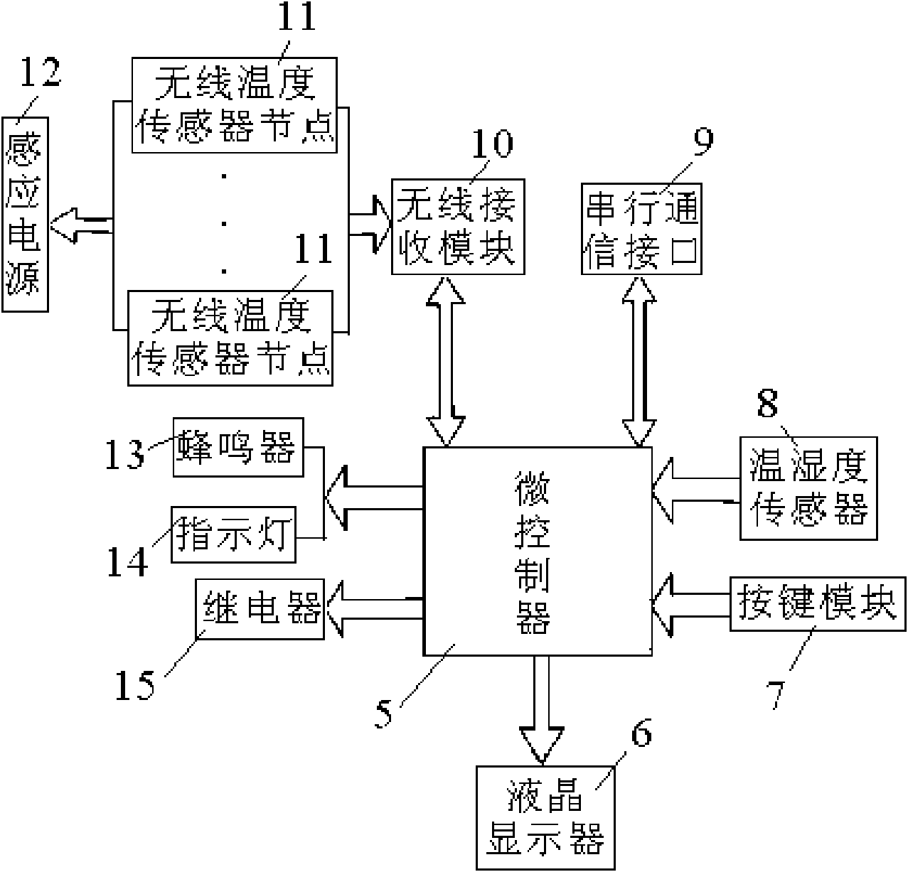
[0027] The structure of monitoring extension 1 in the monitoring system of the present invention, as figure 2 As shown, it includes microcontroller 5, and microcontroller 5 is connected with liquid crystal display 6, key module 7, temperature and humidity sensor 8, serial communication interface 9, wireless receiving module 10, buzzer 13, indicator light 14 and relay 15 respectively The wireless receiving module 10 is connected to the 9 wireless temperature sensor nodes 11 in a w...
PUM
 Abstract
Description
Claims
Application Information