Thermal power measurement device

A technology for measuring devices and thermal power, applied in the directions of measuring devices, measuring electricity, measuring electrical variables, etc., can solve the problems of large signal and error of the device, no temperature equalization system installed in the calorimetric device, and low accuracy of ambient temperature control, and achieve Effects of reduced position dependence, good contact, and improved stability

Active Publication Date: 2009-11-11
INST OF CHEM CHINESE ACAD OF SCI
View PDF5 Cites 22 Cited by
  • Summary
  • Abstract
  • Description
  • Claims
  • Application Information

AI Technical Summary

Problems solved by technology

The first two large-volume thermal power measurement devices have relatively large background signals and errors due to the low accuracy of ambient temperature control outside the device and the lack of a temperature equalization system inside the calorimetric device.
The latter power measurement device is suitable for the measurement of thermal power in slow-changing processes such as nuclear radiation with a long half-life, and is not suitable for measuring rapid exothermic or endothermic processes such as chemical reactions.
Ch

Method used


Image

  • Thermal power measurement device
  • Thermal power measurement device
  • Thermal power measurement device

Examples


Embodiment Construction

[0018] The present invention will be described in detail below in conjunction with the accompanying drawings and embodiments.

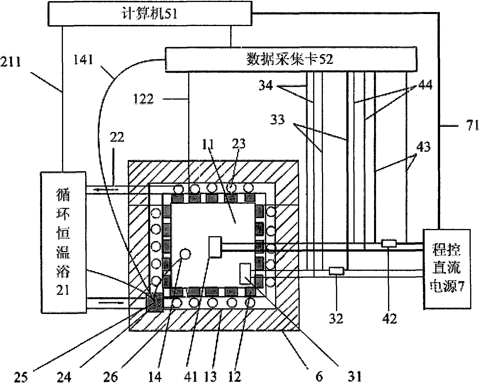
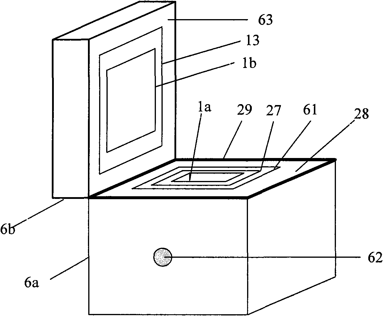
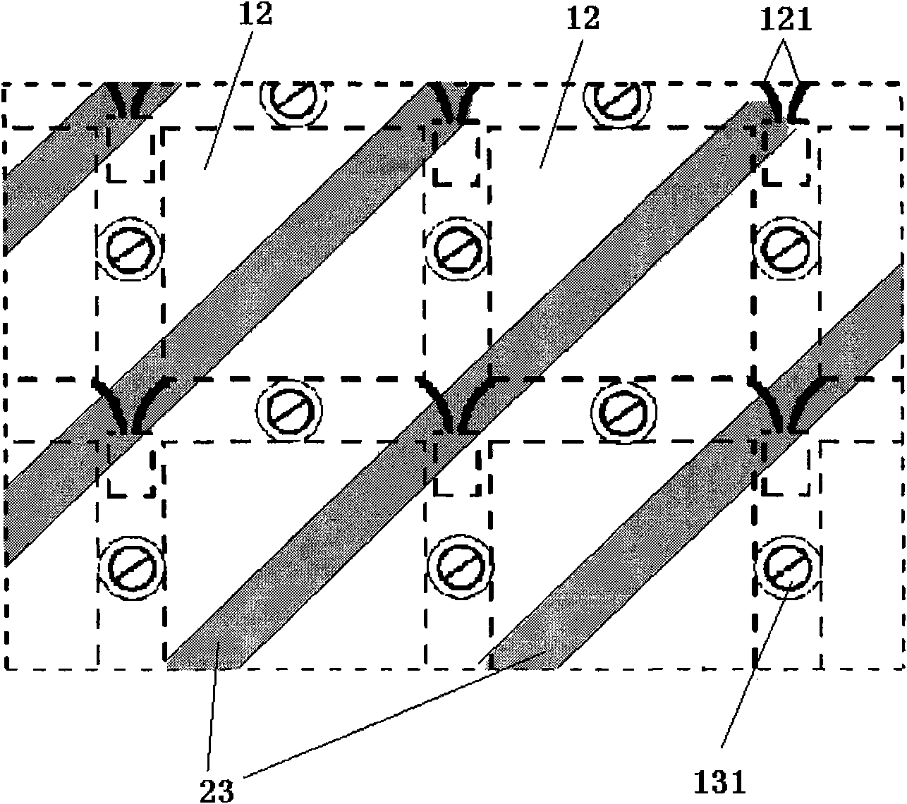
[0019] Such as figure 1 , figure 2 As shown, the present invention includes a calorimeter 1 , a constant temperature insulation system 2 , a temperature uniform system 3 , a calibration system 4 , a signal processing and control system 5 and a box body 6 . Among them, the calorimeter 1 is a three-layer nested compound chamber structure as a whole, which includes a lower cylinder body 1a and an upper top cover 1b; the box 6 is wrapped outside the calorimeter 1, including the box body 6a and the box body The cover 6b corresponds to the upper and lower structure of the calorimeter 1 . The signal processing and control system 5 includes a computer 51 and a data acquisition card 52 . The calorimeter 1 is divided into a sample chamber 11 , a semiconductor thermoelectric module 12 and an outer wall 13 from the inside to the outside. The sample chamber 1...


PUM


Abstract

A thermal power measurement device is characterized in that the device comprises a calorimetry cylinder, a constant-temperature and heat-insulation system, a temperature equalization system, a calibration system, a signal processing and controlling system and a box body, wherein the calorimetry cylinder is a three-layer embedded composite structure; the inner-most layer is a sample chamber, the middle layer is semiconductor thermoelectric modules that are connected in series and the external wall is a constant-temperature layer; the sample chamber is internally provided with a thermocouple and a thermal resistor; the semiconductor thermoelectric modules are fixedly arranged between the sample chamber and the external wall by a mechanical method; the constant-temperature and heat-insulation system comprises a constant-temperature system and a heat insulation system; the constant-temperature system comprises a circular constant-temperature bath and a red copper fluid pipe; the red copper fluid pipe is closely attached to the external wall of the calorimetry cylinder; the inlet of the red copper fluid pipe is connected with the circular constant-temperature bath by a constant-temperature trough; the constant-temperature trough is internally provided with a remote temperature probe that is connected with the circular constant-temperature bath; the temperature equalization system comprises a fan that is arranged in the sample chamber; the calibration system comprises the thermal resistor; and the signal processing and controlling system comprises a computer and a data collecting card and is used for collecting signals in real time and controlling the fan power, calibration power and water bath temperature.

Description

technical field [0001] The invention relates to a measuring device, in particular to a thermal power measuring device. Background technique [0002] A common thermal conductivity thermal power measurement device includes a sample chamber, a thermopile composed of thermocouples connected in series, and an external constant temperature layer from the inside to the outside. During measurement, the sample to be tested is placed in a closed sample chamber surrounded by a thermopile, and the heat flow generated or absorbed by the sample to be tested is transferred from the sample chamber to the outer wall, and an electrical signal proportional to the heat flow is generated on the thermopile. The thermal power of the sample to be tested can be obtained from the magnitude of the signal. [0003] In this process, the following problems need to be solved: due to the uneven temperature distribution in the sample chamber, the electrical signal response depends on the position of the sa...

Claims


Application Information

Patent Timeline
IPC IPC(8): G01N25/20G01R31/36
Inventor 张武寿
Owner INST OF CHEM CHINESE ACAD OF SCI
Why Eureka
Try Eureka