
Cooling system and projecting apparatus adopting same

A cooling system and projection device technology, applied in projection devices, cooling/ventilation/heating transformation, optics, etc., can solve problems such as heat accumulation and insufficient cooling of projection devices, so as to ensure effective work, good dust-proof effect, and realize cooling effect

Active Publication Date: 2009-11-11
SANYO TECH CENT SHENZHEN +1
View PDF0 Cites 18 Cited by
  • Summary
  • Abstract
  • Description
  • Claims
  • Application Information

AI Technical Summary

Problems solved by technology

[0003] In order to solve the problem that the projection device in the prior art reduces the setting of the air inlet and the air outlet in order to achieve the dust-proof effect, thereby causing insufficient cooling and local hot gas accumulation in the projection device, the present invention provides a cooling system and adopts the cooling system. The projection device of the system, while realizing the dust-proof effect, realizes the sufficient cooling of the heat-generating components inside the projection device and avoids the accumulation of local heat

Method used


Image

  • Cooling system and projecting apparatus adopting same
  • Cooling system and projecting apparatus adopting same
  • Cooling system and projecting apparatus adopting same

Examples


Embodiment Construction

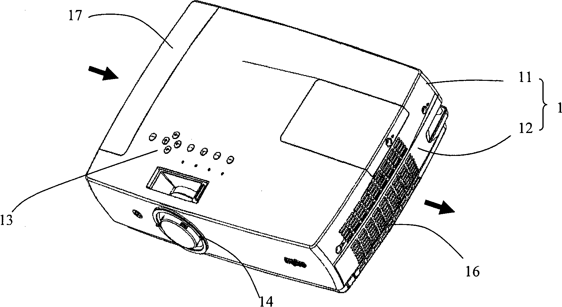
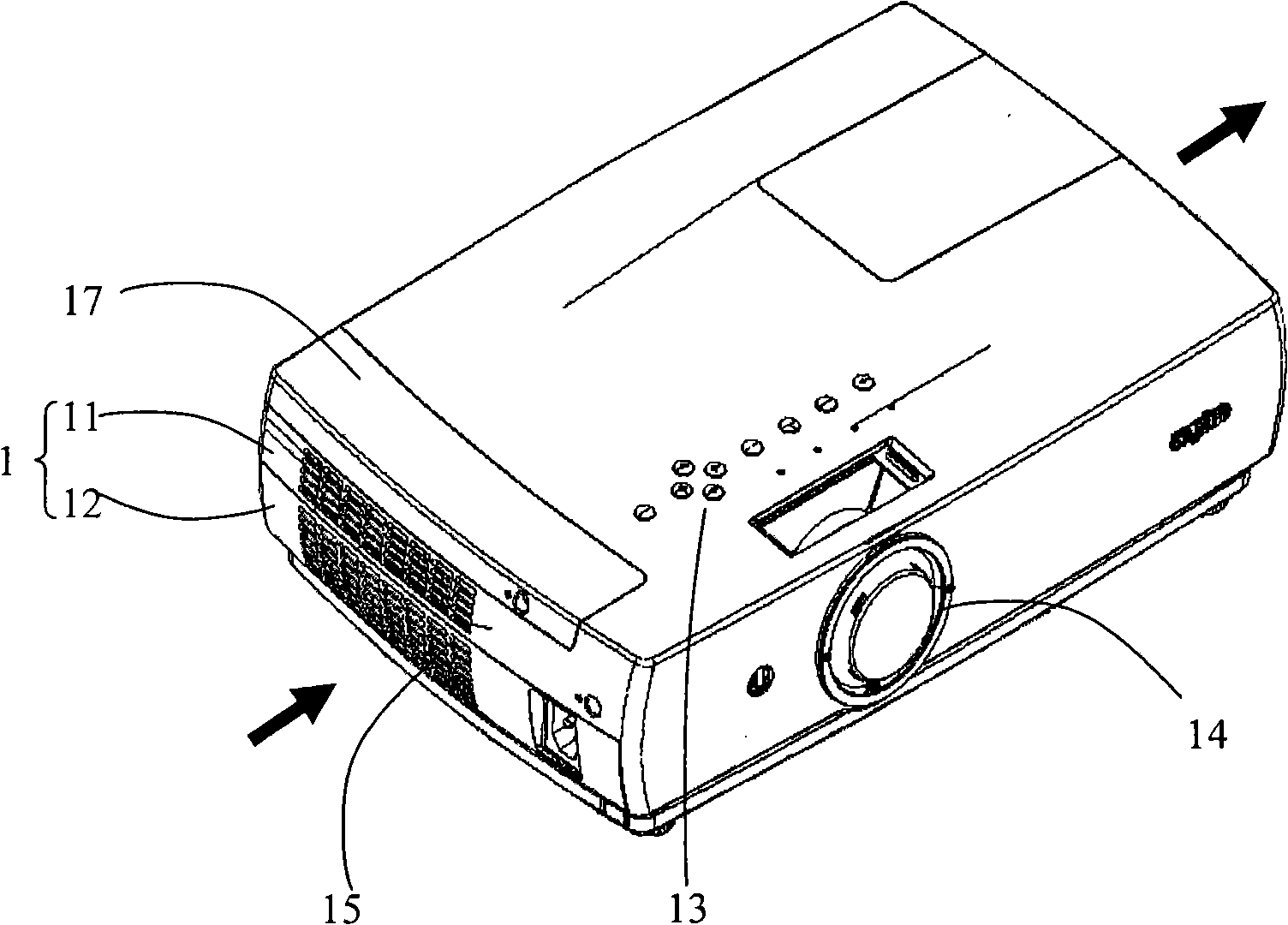
[0041] Embodiments of the cooling system and projection device of the present invention will be described in detail below with reference to the accompanying drawings.

[0042] In the following, a liquid crystal projection device (also referred to as a liquid crystal projection device, projector, etc.) is taken as an example to describe in detail with reference to the accompanying drawings, but the present invention is not limited to a liquid crystal projection device. Any suitable projection device can be adapted to the cooling system of the present invention. In the instructions below, the figure 2 The image projection direction of the illustrated liquid crystal projection device is set to the front, and left and right are defined toward the front surface of the liquid crystal projection device. In addition, the terms "rear", "bottom", "side" and similar terms used herein are relative and exemplary. They can vary depending on how the projection device is used and placed. ...


PUM


Abstract

The invention provides a cooling system and a projecting apparatus adopting the same. The projecting apparatus comprises a shell and also comprises optical components, a lamp bulb assembly and a power supply component which are arranged in the shell. The cooling system comprises an air inlet, an air outlet, a dust preventing component, a cooling air channel, a lamp bulb component air-cooling unit, a power supply air-cooling unit and an exhauster; the air inlet and the air outlet are respectively arranged at two opposite narrower sides of the shell; the dust preventing component is arranged in the shell and clings to the air inlet; the cooling air channel clings to the dust preventing component and is internally provided with a plurality of fans and air guiding pipes which correspond to the fans, wherein the air guiding pipes lead to all the optical components; the lamp bulb component air-cooling unit and the power supply air-cooling unit collect the air-cooled exhausted air at the air outlet; and the exhauster is arranged in the shell and near to the air outlet and discharges the collected exhausted air out of the shell. When the dust is prevented, heating components in the projecting device are fully cooled, and local hot air accumulation is avoided.

Description

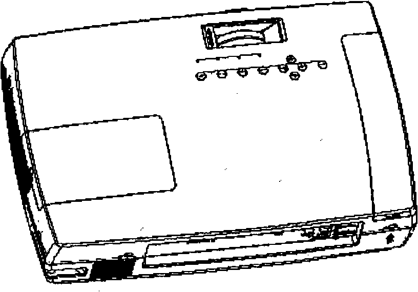
Background technique [0001] With the development of science and technology, projection devices have more and more functions, and users are more and more convenient to use, but the requirements for the design of projection devices are getting higher and higher. [0002] Such as figure 1 Shown is a schematic diagram of the structure of the projection device. In order to achieve a good cooling effect inside the casing of the projection device, multiple vents are often provided on the side of the casing. However, too many air vents easily lead to the accumulation of dust inside the chassis, which affects the normal operation of internal components and also brings difficulties to the maintenance of the projection device. For some projection devices, due to the requirement to achieve the effect of dust prevention, the ventilation openings of the whole machine need to be set as few as possible, which directly leads to the problem that the air volume inside the machine is insufficien...

Claims


Application Information

Patent Timeline
Patent Type & Authority Applications(China)
IPC IPC(8): G03B21/16H05K7/20
Inventor 颜燕云梁接明夏正伟孔祥飞王云毛小林陈孔锋梁向东黄燕山冈崎昌二莲佛忠志
Owner SANYO TECH CENT SHENZHEN
Learn More