
Eureka
For R&D, Eureka makes reading and utilizing patents & technical documents easy.
Eureka AIR
Designed for self-driven R&D workflows. Generate viable solutions, solve complex R&D challenges, empower your innovation with AI.

Eureka Materials
Designed for material experts only. Revolutionize your material R&D, from search, analyze, to developing new materials.

TechResearch
Generate reliable direction feasibility study reports for your R&D in just a few steps.

TechSeek
Discover and master advanced knowledge NOW. Basics, ideas, possibilities, all at once.

TechMind
As an expert in R&D Theories, TechMind can generates customized viable solutions instantly.

TechRisk
Analyze your overall solution with one click, know your potential R&D risks in advance.

TechMonitor
Get weekly tech updates, stay abreast of the latest tech innovations and key insights.
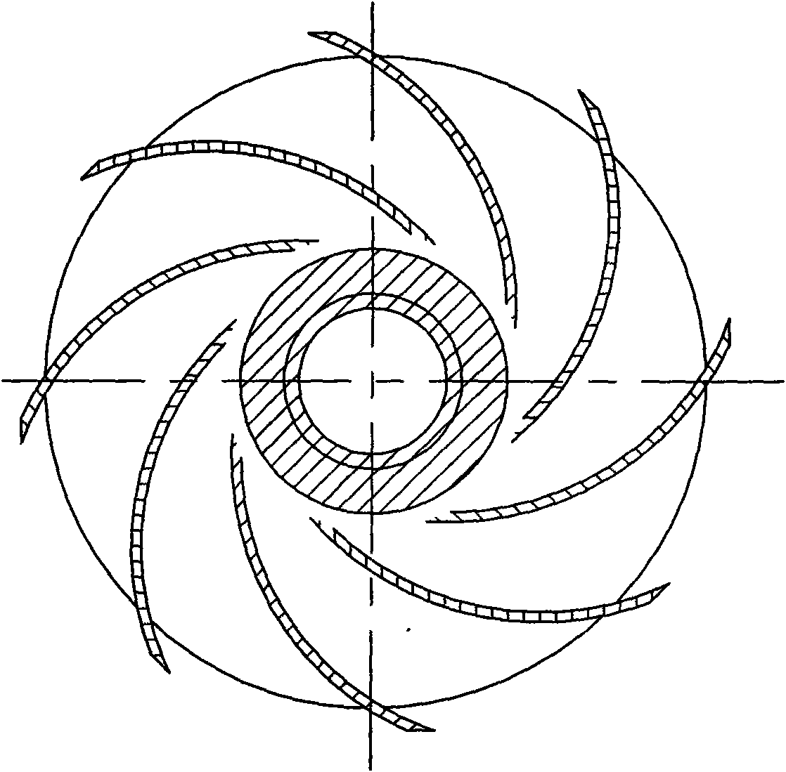
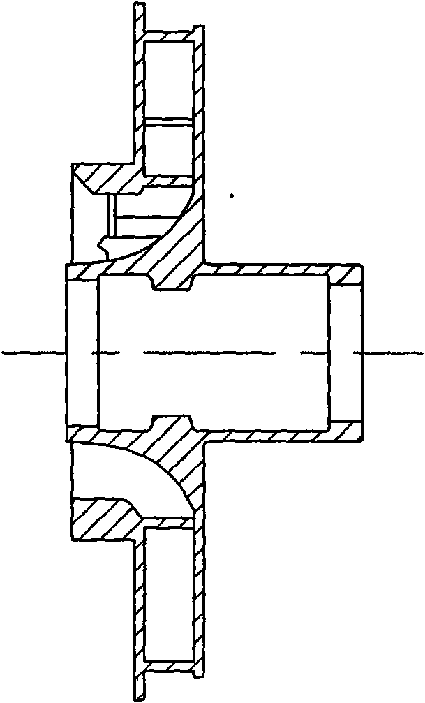
Process for manufacturing shell of impeller of electrical pump
A manufacturing process and impeller technology, which is applied to the components, pumps, and pump components of pumping devices for elastic fluids, can solve the problems of long production cycle, high scrap rate, scrap castings, etc., to improve labor efficiency, improve The effect of yield and short production cycle
- Summary
- Abstract
- Description
- Claims
- Application Information
AI Technical Summary
Problems solved by technology
Method used
Image

Examples
Embodiment 1
[0027] Example 1: To prepare a shell of an electric pump impeller with a flow channel height of 7.5 mm, the steps are as follows:
[0028] 1) Shell making: use zircon powder slurry and mullite powder slurry to apply slurry, hang sand, and dry the impeller wax model layer by layer;
[0029] The zircon powder slurry is obtained as follows: 100kg S830 silica sol in an empty dipping bucket, with 450g wetting agent, 220g defoamer, adding 380kg 300 mesh zircon powder; when adding 300 mesh zircon powder , While adding it, manual auxiliary stirring is used to prevent the 300 mesh zircon powder from accumulating and agglomerating during the addition. After the 300 mesh zircon powder is added, the flow rate is measured after 2 hours and the flow rate is 32 seconds. Add 1.2Kg zircon powder , After fully stirring for 26 hours through the rotation of the dipping bucket, the flow rate is measured again for 35 seconds.
[0030] The mulberry powder slurry is obtained by adding 90kg S1420 silica s...
Embodiment 2
[0037] Embodiment 2: An electric pump impeller with a flow channel height of 6mm, the steps are the same as in embodiment 1, wherein the processes involved in step 1) are shown in Table 2:
[0038] Table 2
[0039] Level
[0040] Slurry 20
[0041] The test proves that the 75 impellers cast by the shells manufactured in Example 1 and Example 2 are all qualified, and the shell in the flow channel is easily removed during the sand cleaning process of the vibrating shell.
PUM
 Abstract
Description
Claims
Application Information
 - R&D Engineer
- R&D Manager
- IP Professional
- Industry Leading Data Capabilities
- Powerful AI technology
- Patent DNA Extraction
Browse by: Latest US Patents, China's latest patents, Technical Efficacy Thesaurus, Application Domain, Technology Topic, Popular Technical Reports.
© 2024 PatSnap. All rights reserved.Legal|Privacy policy|Modern Slavery Act Transparency Statement|Sitemap|About US| Contact US: help@patsnap.com