Integrated coupling device for flue gas desulfurization and dedusting

A technology of desulfurization and dust removal and coupling devices, which is applied in combined devices, chemical instruments and methods, and separation of dispersed particles, can solve the problems of uneven distribution of flow field, influence of spray washing effect, and low primary utilization rate of circulating fluid, etc., to achieve Efficient desulfurization and dust removal, lower liquid-gas ratio and airflow resistance, and improved airflow distribution

Active Publication Date: 2009-11-25
SHANGHAI JIAO TONG UNIV
View PDF1 Cites 16 Cited by
  • Summary
  • Abstract
  • Description
  • Claims
  • Application Information

AI Technical Summary

Problems solved by technology

However, since the sprayed desulfurization liquid mostly flows along the tower wall to the overflow tank of the bottom swirl plate before reaching the lower bottom swirl plate, this part of the liquid can no longer be use

Method used


Image

  • Integrated coupling device for flue gas desulfurization and dedusting
  • Integrated coupling device for flue gas desulfurization and dedusting
  • Integrated coupling device for flue gas desulfurization and dedusting

Examples


Embodiment 1

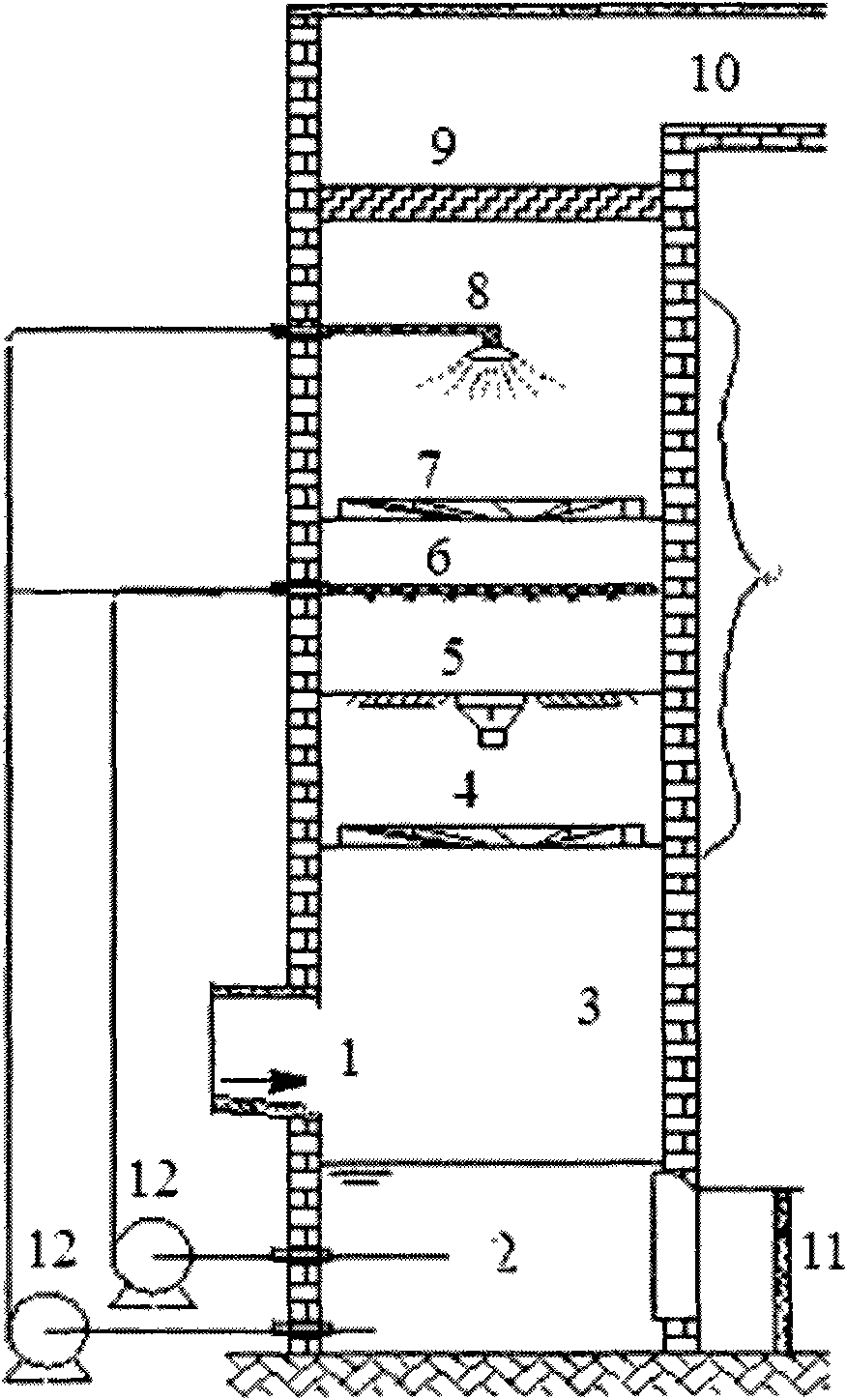
[0021] Such as figure 1 As shown, this embodiment includes: tangential flue gas inlet 1, tower body 2, water film dust removal section 3, bottom swirl plate 4, inward spray plate 5, spray layer and nozzle 6, lower defogging plate 7, spare Spray pipe 8, upper demister 9, flue gas outlet 10, desulfurization liquid discharge port 11 and desulfurization circulation pump 12, wherein: the tangential air inlet is located at the lower end side of the tower body, the bottom swirl plate, the inward injection plate, The spray layer, the first defogging plate and the second defogging plate are arranged in parallel in the tower body from bottom to top in sequence, and the flue gas outlet is located at the top of the tower body.

[0022] The special-shaped overflow pipe of the conventional swirl plate is removed from the bottom swirl plate, and a gap of 6mm is left between its outer edge and the tower wall.

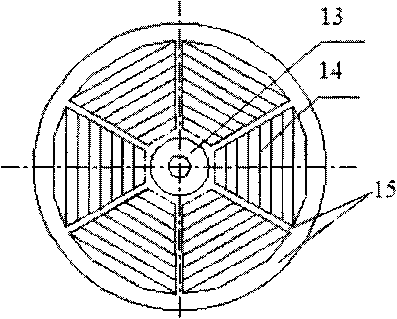
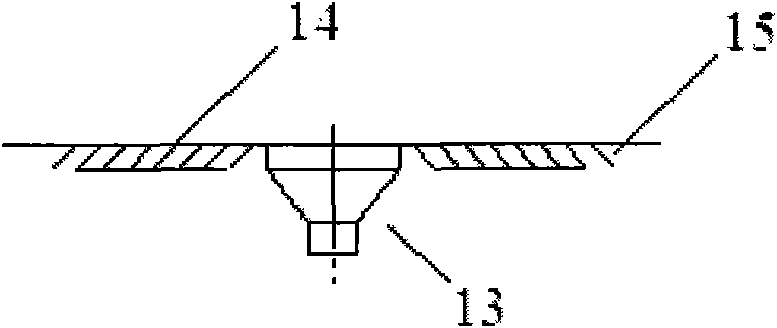
[0023] As shown in Figure 2, the inward jetting plate 5 is provided with: a centr...

Embodiment 2

[0035] For a coal-fired boiler with an evaporation capacity of 20t / h, the designed flue gas volume is 55,000m 3 / h, flue gas temperature is 150°C, inlet flue gas SO 2 Concentration up to 2200mg / Nm 3 , soot content 1200mg / Nm 3 . The device of the present invention adopts the figure 1 For the device shown, the inner diameter of the tower is 2200mm. Sodium-calcium double-alkali flue gas desulfurization process is adopted. The vane elevation angle of the bottom swirl plate is 28°, and the opening ratio is 32%; the elevation angle of the inward jet plate is 32°, and the opening ratio is 36%.

[0036] When the boiler load is 90%, the liquid-gas ratio is 1.8L / m 3 The measured desulfurization efficiency is 96.3%, and the dust removal efficiency is greater than 97% (the dust concentration in the outlet flue gas is lower than 50mg / Nm 3 ). The airflow resistance of the whole tower is only about 800Pa.

Embodiment 3

[0037]Example 3 uses the same structure as Example 1 to treat the coal-fired flue gas of a 40t / h coal-fired boiler. The flue gas is pre-dedusted by a multi-tube dust collector, and then desulfurized and further dedusted by a magnesium oxide desulfurization process. The amount of flue gas treated is 120000m 3 / h, sulfur dioxide concentration 3500mg / Nm 3 . The diameter of the absorption tower is 3500mm. The results show that when the liquid-gas ratio is 2.2L / m 3 , the desulfurization rate was 97%. No fouling and clogging occurred during the continuous operation of the equipment for 6 months.


PUM

PropertyMeasurementUnit
Elevation angleaaaaaaaaaa
Widthaaaaaaaaaa
Airflow resistanceaaaaaaaaaa

Abstract

The invention, which belongs to the field of flue gas desulfurization technique, provides an integrated coupling device for flue gas desulfurization and dedusting, which includes: a tower body, a tangential intake port, a flue gas exit port, a bottom layer rotational flow board, a inward sprinkler plate, a spraying layer, a lower defogging board and a upper defroster, wherein a central overflow tube is located in the center of the inward sprinkler plate, several injection blades are fixed and equipped on the outer edge of the central overflow tube angularly from layer to layer in a regular polygon mode, and the support plate tendon is connected with double ends of every piece of injection blade in a fixed connection. The invention uses the inward sprinkler plate in an unique design, and couples the spraying method and the rotational flow method in an organic combination, the inward sprinkler plate has multiple efficacies of desulphurization, dedusting, air flow distribution improvement as well as doctor solution influx, thereby the device provided by the invention has high-efficient desulphurization and dedusting functions, moreover reduces the liquid-gas ratio and airflow resistance obviously.

Description

technical field [0001] The invention relates to a device in the technical field of boiler flue gas desulfurization, in particular to an integrated coupling device for flue gas desulfurization and dust removal. Background technique [0002] my country is the country with the largest coal consumption in the world, and the total amount of sulfur dioxide emitted by coal burning ranks first in the world. Therefore, the Chinese government is gradually implementing strict coal-fired flue gas emission standards, and implementing flue gas desulfurization and dust removal treatment for power plant boilers, industrial boilers and kilns. [0003] There are various flue gas desulfurization methods. Currently, wet desulfurization devices widely used include bottom swirl plate tower, spray tower, bubble tower, Venturi absorber, etc.; large-scale thermal power desulfurization mostly uses spray tower, because of its gas path It has the least resistance and can adapt to different boiler load...

Claims


Application Information

Patent Timeline
IPC IPC(8): B01D50/00
Inventor 晏乃强瞿赞乔少华吴忠标
Owner SHANGHAI JIAO TONG UNIV
Why Eureka
Try Eureka