Narrow slit effect quenching clamper
An effect and fixture technology, applied in the field of heat treatment of metal materials, can solve problems such as difficulty in adapting to production development and product diversity, long time and capital, etc., and achieve the effects of low manufacturing cost, convenient operation and good adaptability
- Summary
- Abstract
- Description
- Claims
- Application Information
AI Technical Summary
Problems solved by technology
Method used
Image

Examples
Embodiment 1
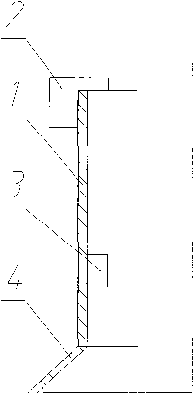
[0022] As shown in Figure 1 (a), the present embodiment comprises: a cylinder body 1, a hanging plate 2, a positioning plate 3, and a drainage port 4, wherein: the hanging plate 2 is fixed on the top of the cylinder body 1, and the plane of the hanging plate 2 is perpendicular to On the horizontal plane, the positioning plate 3 is fixed on the inner side of the cylinder body 1, the plane of the positioning plate 3 is perpendicular to the horizontal plane and the surface of the cylinder body 1, and the drainage port 4 is fixed on the bottom of the cylinder body 1.
[0023] The cylinder 1 is a cylindrical cylinder that hangs on the cylindrical workpiece or the outside of the cylindrical workpiece, the positioning plate 3 is fixed on the inner side of the cylinder 1, and the drainage port 4 is a conical structure with a diameter from It gradually expands from top to bottom, so that the distance between the bottom of the drainage port 4 and the surface of the workpiece 5 is greater...
Embodiment 2
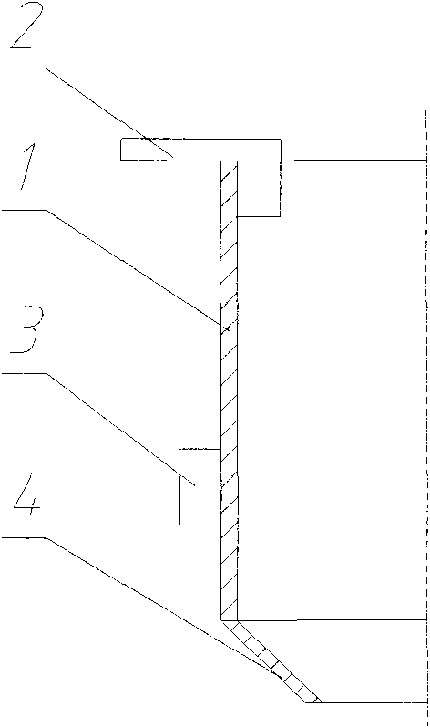
[0026] As shown in Figure 2 (a), the present embodiment comprises: a cylinder body 1, a hanging plate 2, a positioning plate 3, and a drainage port 4, wherein: the hanging plate 2 is fixed on the top of the cylinder body 1, and the plane of the hanging plate 2 is perpendicular to On the horizontal plane, the positioning plate 3 is fixed on the outside of the cylinder body 1, the plane of the positioning plate 3 is perpendicular to the horizontal plane and the surface of the cylinder body 1, and the drainage port 4 is fixed on the bottom of the cylinder body 1.
[0027] The cylinder body 1 is a cylinder suspended on the inside of the cylindrical workpiece 5, the positioning plate 3 is fixed on the outside of the cylinder body 1, and the drainage port 4 is an inverted cone structure, and its diameter gradually decreases from top to bottom. Make the gap between the bottom of the drainage port 4 and the inner wall surface of the workpiece 5 larger than the gap between the cylinder ...
Embodiment 3
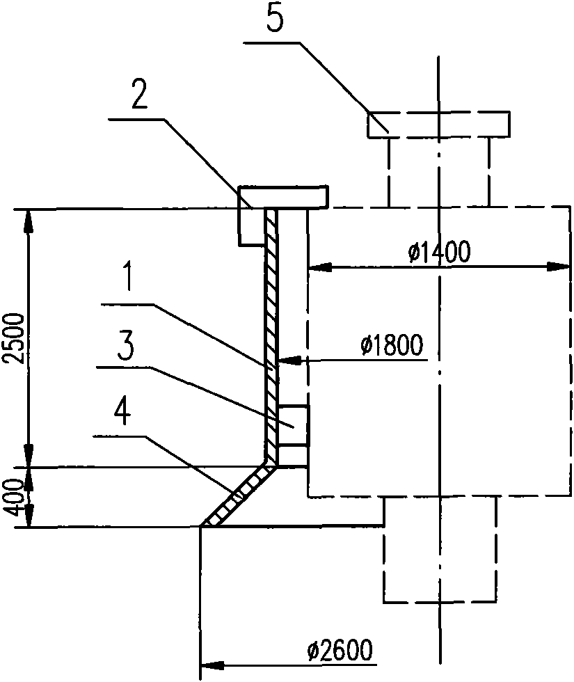
[0030] As shown in Figure 3 (a), the present embodiment comprises: a cylinder body 1, a hanging plate 2, a positioning plate 3, and a drainage port 4, wherein: the hanging plate 2 is fixed on the top of the cylinder body 1, and the plane of the hanging plate 2 is perpendicular to On the horizontal plane, the positioning plate 3 is fixed on the inner side of the cylinder body 1, the plane of the positioning plate 3 is perpendicular to the horizontal plane and the surface of the cylinder body 1, and the drainage port 4 is fixed on the bottom of the cylinder body 1.
[0031] The cylinder body 1 has a rectangular cross section, the positioning plate 3 is fixed on the inside of the cylinder body 1, the cylinder body 1 is suspended on the outside of the rectangular workpiece 5, and the drainage port 4 is tapered, and its cross section gradually expands from top to bottom .
[0032] As shown in Figure 3(b), the slit effect quenching fixture is made of 5mm steel plate, the cross-secti...
PUM
| Property | Measurement | Unit |
|---|---|---|
| Thickness | aaaaa | aaaaa |
| Heat transfer coefficient | aaaaa | aaaaa |
Abstract
Description
Claims
Application Information
 - R&D
- Intellectual Property
- Life Sciences
- Materials
- Tech Scout
- Unparalleled Data Quality
- Higher Quality Content
- 60% Fewer Hallucinations
Browse by: Latest US Patents, China's latest patents, Technical Efficacy Thesaurus, Application Domain, Technology Topic, Popular Technical Reports.
© 2025 PatSnap. All rights reserved.Legal|Privacy policy|Modern Slavery Act Transparency Statement|Sitemap|About US| Contact US: help@patsnap.com