
Demodulation method and device for optical distance variation of optical fiber interferometer sensor

An optical fiber interferometer and optical path change technology, which is applied in the direction of using optical devices to transmit sensing components, can solve the requirements of reducing the spectral sampling resolution of interferometer sensors and the problems of high cost, and achieve lower demodulation costs, lower requirements, and higher cost. Effects of high sensitivity or resolution

Active Publication Date: 2009-11-25
UNIV OF ELECTRONICS SCI & TECH OF CHINA
View PDF0 Cites 23 Cited by
  • Summary
  • Abstract
  • Description
  • Claims
  • Application Information

AI Technical Summary

Problems solved by technology

[0004] The technical solution to be solved by the present invention is to provide a demodulation method for the optical path change of the optical fiber interferometer sensor, which can greatly reduce the requirements for the spectral sampling resolution of the interferometer sensor, and avoid the high cost of traditional spectral demodulation methods. disadvantages, while having high demodulation resolution

Method used

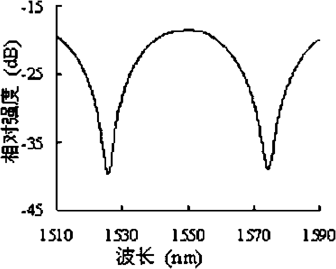

Image

  • Demodulation method and device for optical distance variation of optical fiber interferometer sensor
  • Demodulation method and device for optical distance variation of optical fiber interferometer sensor
  • Demodulation method and device for optical distance variation of optical fiber interferometer sensor

Examples


Embodiment Construction

[0012] The demodulation method of the present invention is: 1) detecting the spectrum of the optical fiber interferometer sensor. There are two ways to detect the spectrum of the fiber optic interferometer: the first is to pass the light emitted by the broadband light source or multi-wavelength light source through a coupler or circulator, and then inject the light into the fiber optic interferometer sensor, and pass the light from the fiber optic interferometer sensor. The reflected light signal or the transmitted light signal returns to the other end of the above-mentioned coupler or circulator, and then enters the spectrum detection device to obtain the spectrum of the fiber optic interferometer sensor; the second is to pass the light emitted by the wavelength tunable light source through the coupler or After the circulator, light is injected into the fiber optic interferometer sensor, and the reflected light signal or transmitted light signal of the fiber optic interferomet...


PUM


Abstract

The present invention provides a demodulation method for the optical distance variation of an optical fibre interferometer sensor, including steps of (1) detecting the spectrum of the optical fiber interferometer sensor; (2) transmitting the detected spectrum to a computer for a Fourier transformation or Z spectrum conversion to obtain an amplitude spectrum and a phase spectrum of an optical fiber interferometer sensor reflected signal; (3) obtaining an approx center frequency of the optical fiber interferometer sensor from the amplitude spectrum and then fixing the frequency point to monitor the change of the point phase; obtaining the optical distance change of the optical fiber interferometer sensor by the phase spectrum. By monitoring the phase change around the center frequency point in the phase spectrum after the optical spectrum and the frequency spectrum conversion of the optical fiber interferometer sensor, it is capable of obtaining the optical distance change of the interferometer sensor, comparing with the traditional detection of the change of the intensity frequency spectrum center frequency, the sensor center frequency point of the phase spectrum is more sensitive to the optical distance difference, thus the invention has a high sensitivity or resolution.

Description

technical field [0001] The invention belongs to the technical field of optical fiber sensing, and in particular relates to a demodulation method and a device for optical path change of an optical fiber interferometer sensor. Background technique [0002] Optical fiber sensors have a series of advantages such as safety, immunity to electromagnetic interference, easy networking and long-distance telemetry, and suitable for harsh environments, and have gradually become one of the mainstream development directions of the new generation of sensors. [0003] Optical fiber interferometer sensing demodulation schemes can be divided into two categories: intensity demodulation and phase demodulation. The intensity demodulation method cannot be used for high-precision measurement due to its susceptibility to external interference. Phase demodulation can obtain high-resolution cavity length variation demodulation. At present, phase demodulation methods include fringe counting method, ...

Claims


Application Information

Patent Timeline
Patent Type & Authority Applications(China)
IPC IPC(8): G01D5/353
Inventor 冉曾令
Owner UNIV OF ELECTRONICS SCI & TECH OF CHINA
Learn More