Transmission duplex interface circuit suitable for compound impedance medium
A technology of interface circuit and output interface circuit, which is applied in the direction of gearbox hybrid circuit and line transmission components, etc., and can solve the problems that the bridge type side tone cancellation technology cannot be popularized and the line impedance changes.
- Summary
- Abstract
- Description
- Claims
- Application Information
AI Technical Summary
Problems solved by technology
Method used
Image
Examples
Embodiment 1
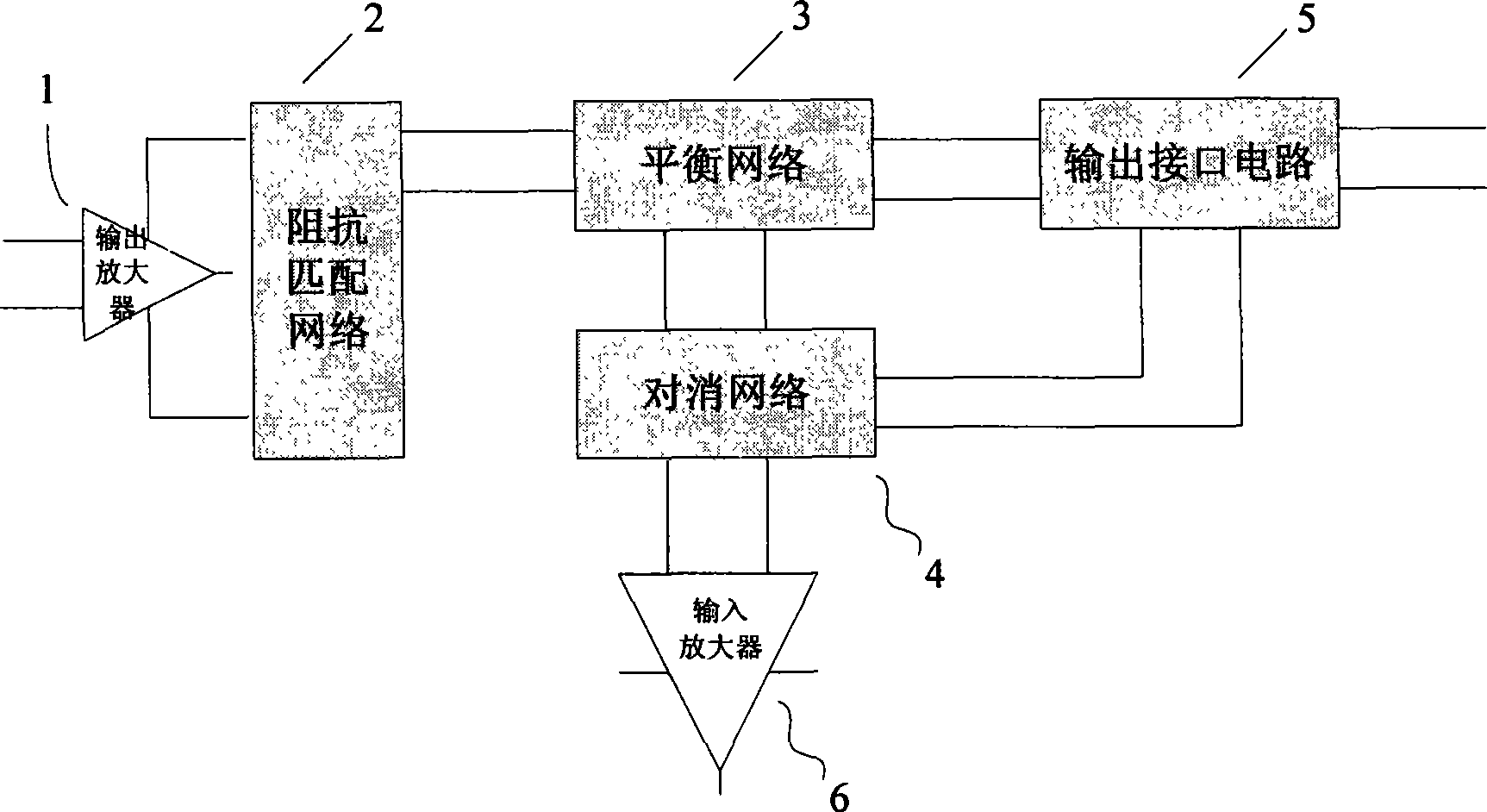
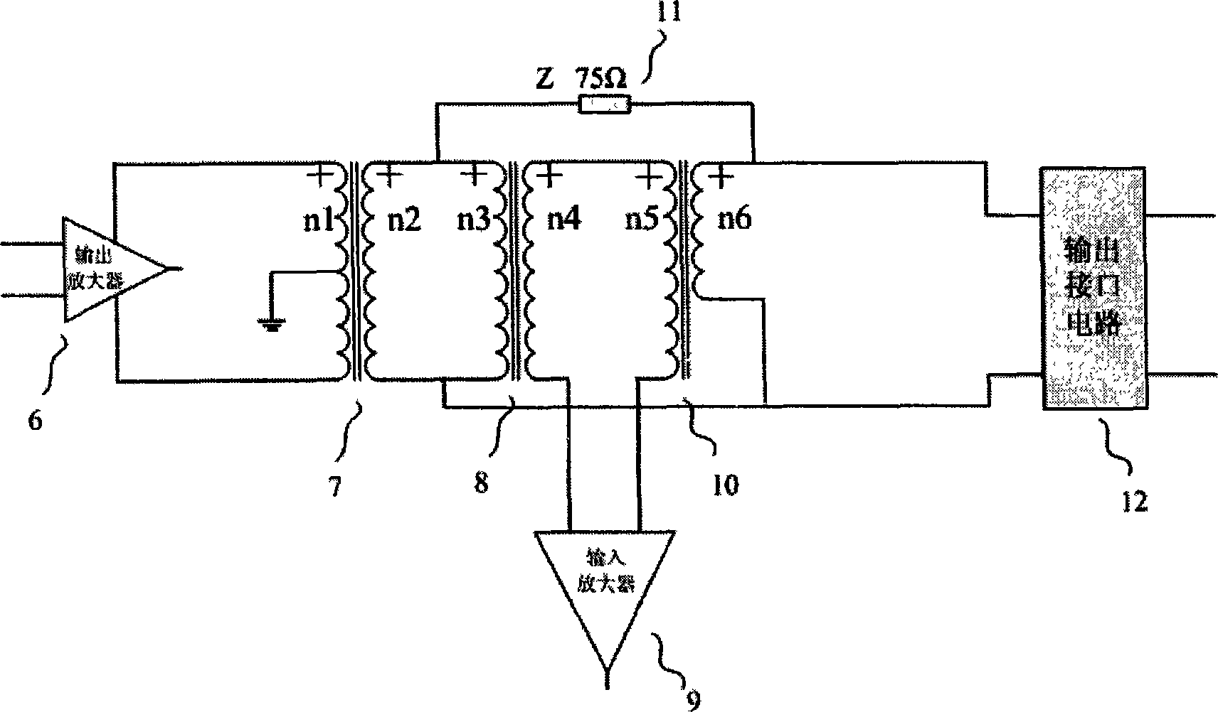
[0019] Such as figure 2 As shown, one of the specific cases for the implementation of a transceiver duplex interface circuit suitable for complex impedance media is characterized in that: the transceiver duplex interface circuit is composed of three transformers, and the impedance matching network consists of an impedance transformation transformer 7 (n1: n2), the balance network 11 is composed of an impedance (75 ohms), and the cancellation network is composed of a transformer 8 (n3:n4) and a transformer 10 (n5:n6). The power signal of the output amplifier 1 is connected to the source stage of the impedance transformation transformer 7 (n1:n2), and the secondary stage of the impedance transformer 7 is connected to the source stage of the transformer 8, and the transformation ratio of the transformer 8 is 1:1. The other path of the secondary side of the impedance converter 7 is connected to the source stage of the transformer 10 and the output interface circuit 12 through the...
Embodiment 2
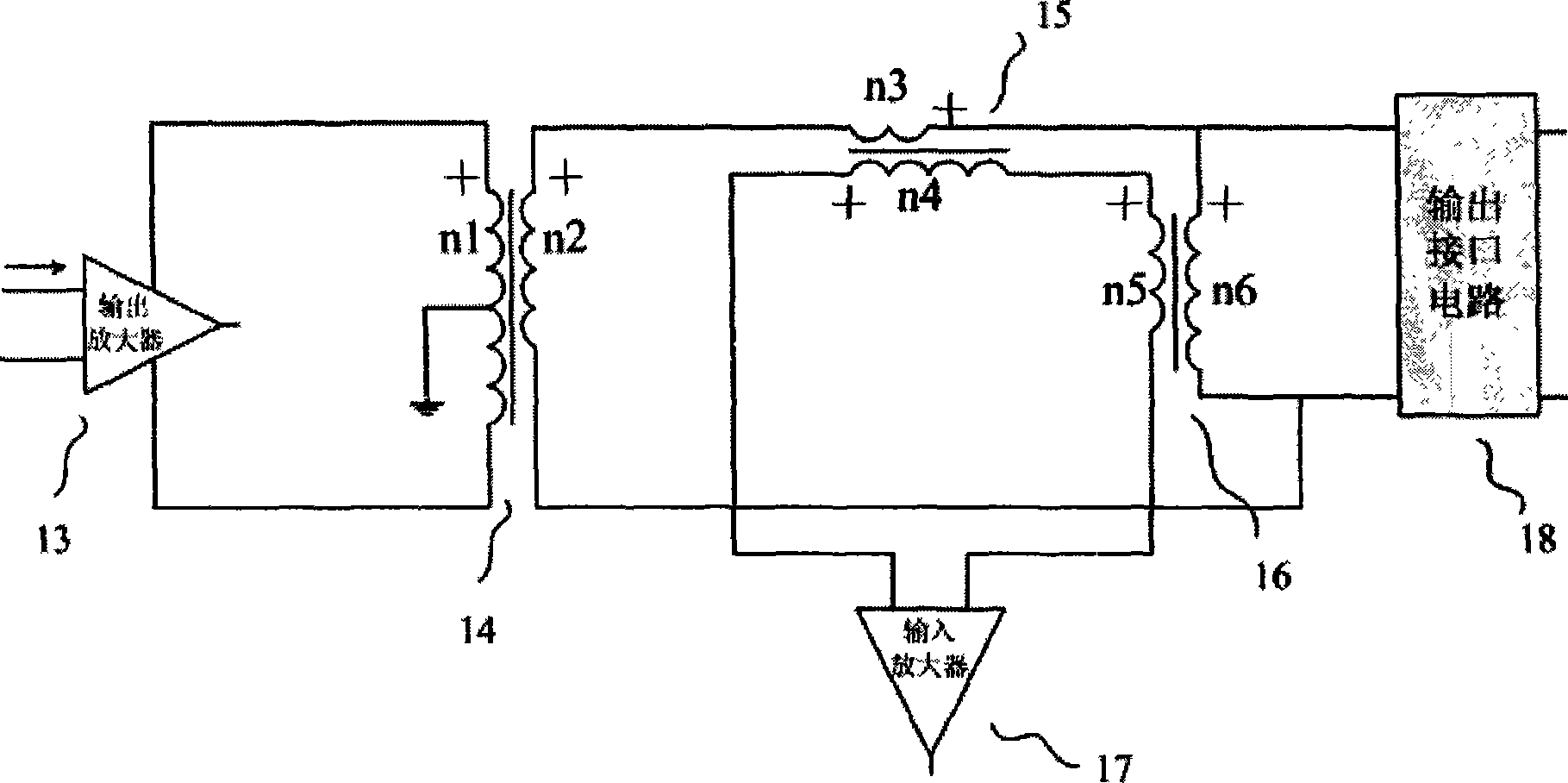
[0024] Such as image 3 As shown, the second specific implementation case of a transceiver duplex interface circuit suitable for complex impedance media is characterized in that: the transceiver duplex interface circuit is composed of three transformers, and the impedance matching network consists of an impedance transformation transformer 14 (n1 :n2), the balance network 15 is composed of the source coil of the transformer 15 (n3:n4), and the cancellation network is composed of the secondary connection of the transformer 15 (n3:n4) and the transformer 16 (n5:n6). The power signal of the output amplifier 13 is connected to the source stage of the impedance converter 14 (n1:n2), the secondary stage of the impedance converter 14 is connected to the source stage of the transformer 8, and the other path is connected to the source stage and output of the transformer 16 through the source coil of the transformer 15 In the interface circuit 18, the secondary of the transformer 15 is ...
PUM
 Abstract
Description
Claims
Application Information
 - R&D
- Intellectual Property
- Life Sciences
- Materials
- Tech Scout
- Unparalleled Data Quality
- Higher Quality Content
- 60% Fewer Hallucinations
Browse by: Latest US Patents, China's latest patents, Technical Efficacy Thesaurus, Application Domain, Technology Topic, Popular Technical Reports.
© 2025 PatSnap. All rights reserved.Legal|Privacy policy|Modern Slavery Act Transparency Statement|Sitemap|About US| Contact US: help@patsnap.com


