Supercharge Your Innovation With Domain-Expert AI Agents!

Strength fitness equipment and method for manufacturing same

A fitness equipment and strength technology, applied in gymnastics equipment, sports accessories, etc., can solve the problems of inability to process, easy contact with the human body, increase safety costs, etc., and achieve the effect of convenient installation and maintenance, simple process, and space saving

Active Publication Date: 2010-09-22
NANTONG IRONMASTER SPROTING IND
View PDF1 Cites 0 Cited by
  • Summary
  • Abstract
  • Description
  • Claims
  • Application Information

AI Technical Summary

Problems solved by technology

[0003] At present, general strength fitness equipment requires simple appearance, beautiful appearance, and safe use, but the steel cable of the transmission part should be easy to install and maintain, and simple to manufacture. The traditional method of threading the steel cable is generally in the open, that is, the steel cable is generally exposed outside Yes, it is easy to come into contact with the human body, pinches and wounds may occur from time to time, and additional devices must be used for protection, which is not only unsafe but also affects the appearance, and also increases the safety cost. Even in the dark, only the sound guide can be used Rod, it takes a long time and the accuracy rate is low, and now processing steel pipes using traditional turning, milling, planing, drilling and other processing machinery is not easy to clamp, the working point is not easy to rotate, the notch is not fixed and it is not easy to process, wire cutting can not achieve The purpose of single-sided forming, and the stamping die has a complex structure and high cost, so cantilever punching can only be used, and the life of the equipment is seriously reduced; some use oxygen cutting, which will cause the size and accuracy of the single-sided notch to fail to meet the requirements, and it is easy to burn wear; there are also some general plasma cutting machines, which require a large turning space and cannot be processed

Method used


Image

  • Strength fitness equipment and method for manufacturing same
  • Strength fitness equipment and method for manufacturing same

Examples


Embodiment Construction

[0010] In order to deepen the understanding of the present invention, the present invention will be further described below in conjunction with the embodiments and accompanying drawings. The embodiments are only used to explain the present invention and do not constitute a limitation to the protection scope of the present invention.

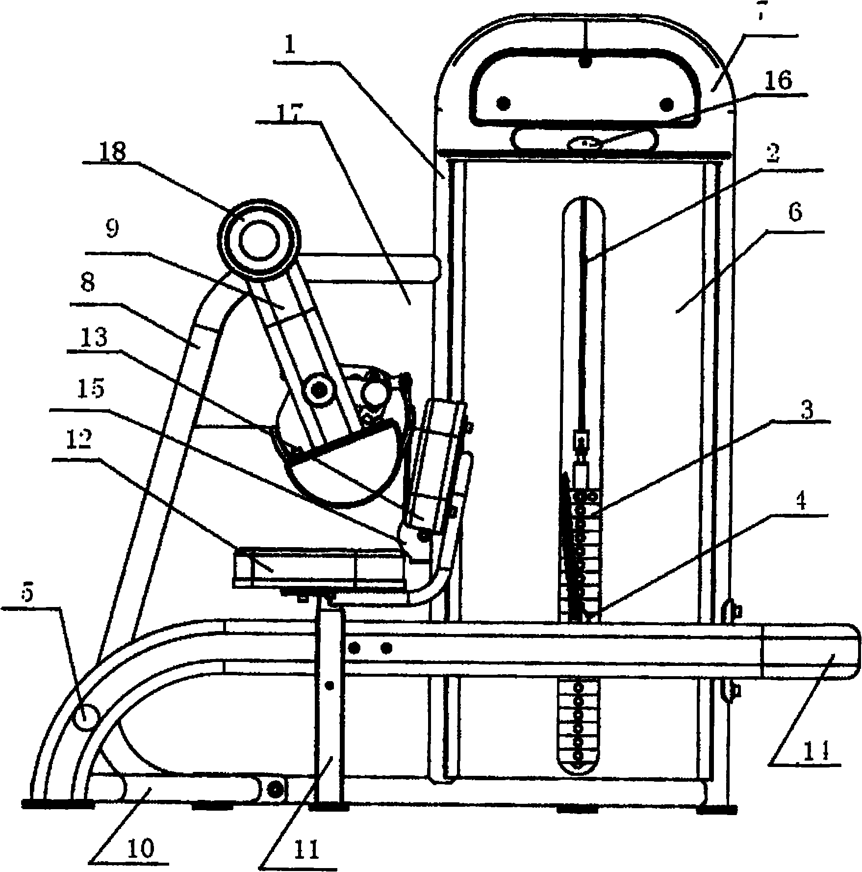
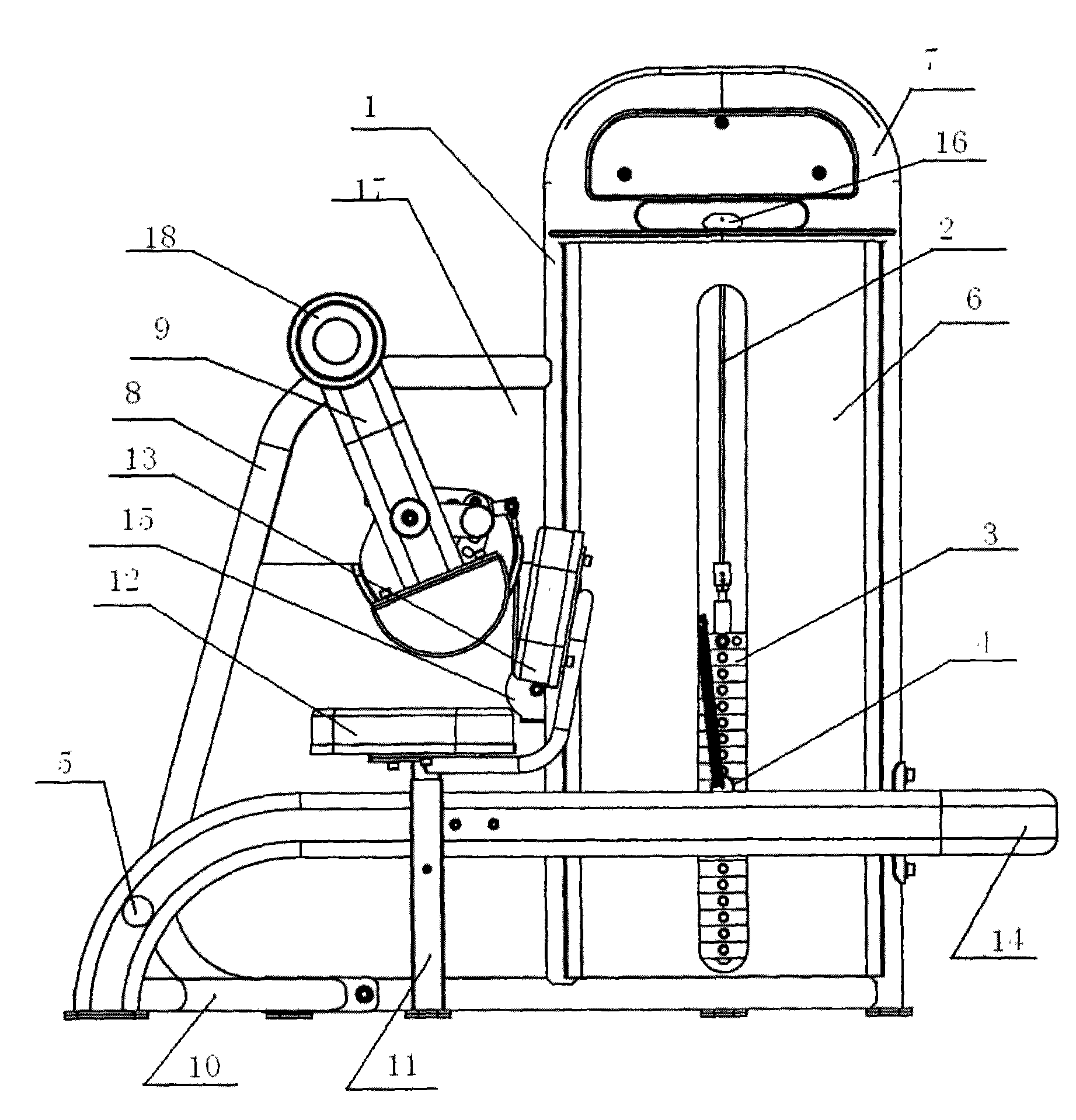
[0011] like figure 1 Shown: a strength fitness equipment, including U-shaped steel pipe 1, steel wire rope 2, selection piece 3, selection pin 4, pedal device 5, translucent baffle 6, protective cover 7, main frame 8, arm pad assembly frame 9 , bottom connection frame 10, cushion group frame 11, seat cushion 12, back cushion 13, rear support frame 14, U-shaped steel pipe 1 can be square pipe, round pipe, oval pipe, D-shaped pipe, and the thickness of U-shaped steel pipe 1 is 1.5 ~5MM, U-shaped steel pipe 1 has an inner single-sided groove at the rounded corner. The inner single-sided groove can be square, circular, triangular, trapezoidal or poly...


PUM


Abstract

The invention discloses strength fitness equipment and a method for manufacturing the same. The strength fitness equipment has the part connecting relation that: the outer side of a U-type steel tube is provided with a semitransparent baffle plate; the upper part of the semitransparent baffle plate is provided with a protective cover; one side of the semitransparent baffle plate is connected witha main frame; the main frame is provided with a lateral plate; the lateral plate is connected with an arm pad group frame; the lower end of the main frame is connected with a cushion group frame through a bottom connecting frame; the cushion group frame is provided with a pedal device; the upper part of the cushion group frame is provided with a cushion and a back cushion; the semitransparent baffle plate is connected with the other side of the cushion group frame through a rear supporting frame; the side and the upside of the semitransparent baffle plate are provided with a first pulley and a second pulley respectively; and a steel wire rope runs through the first pulley, the U-type steel tube and the second pulley and is connected with a selective sheet. The method for manufacturing thestrength fitness equipment comprises: cutting the U-type steel tube, threading the steel wire rope and connecting the parts. The strength fitness equipment has the advantages of simple structure, simple process, safe use, concise shape, space conservation, convenient mounting and maintenance and low cost.

Description

Technical field: [0001] The invention relates to a strength fitness apparatus and a manufacturing method thereof. Background technique: [0002] Strength fitness equipment, also known as anaerobic equipment, is the leading training equipment for exercising skeletal muscle speed, strength, explosive power and bodybuilding. It aims at exercising muscles in relevant parts of the human body by training intensity and duration. [0003] At present, general strength fitness equipment requires simple appearance, beautiful appearance, and safe use, but the steel cable of the transmission part should be easy to install and maintain, and simple to manufacture. The traditional method of threading the steel cable is generally in the open, that is, the steel cable is generally exposed outside. Yes, it is easy to come into contact with the human body, and pinches and wounds may occur from time to time. Additional devices must be used for protection, which is not only unsafe but also affect...

Claims


Application Information

Patent Timeline
Patent Type & Authority Patents(China)
IPC IPC(8): A63B23/12
Inventor 黄承斌施建标
Owner NANTONG IRONMASTER SPROTING IND
Features
  • R&D
  • Intellectual Property
  • Life Sciences
  • Materials
  • Tech Scout
  • Unparalleled Data Quality
  • Higher Quality Content
  • 60% Fewer Hallucinations
Learn More