Device and method for recovering glass reinforced plastic by pyrolysis
A technology of heat recovery device and recovery device, which is applied in special forms of dry distillation, coking oven, petroleum industry, etc., which can solve the problems of waste materials such as hard texture, large volume, and different shapes, and achieve moderate cost, thorough recovery, and good recovery effect Effect
- Summary
- Abstract
- Description
- Claims
- Application Information
AI Technical Summary
Problems solved by technology
Method used
Image
Examples
Embodiment 1
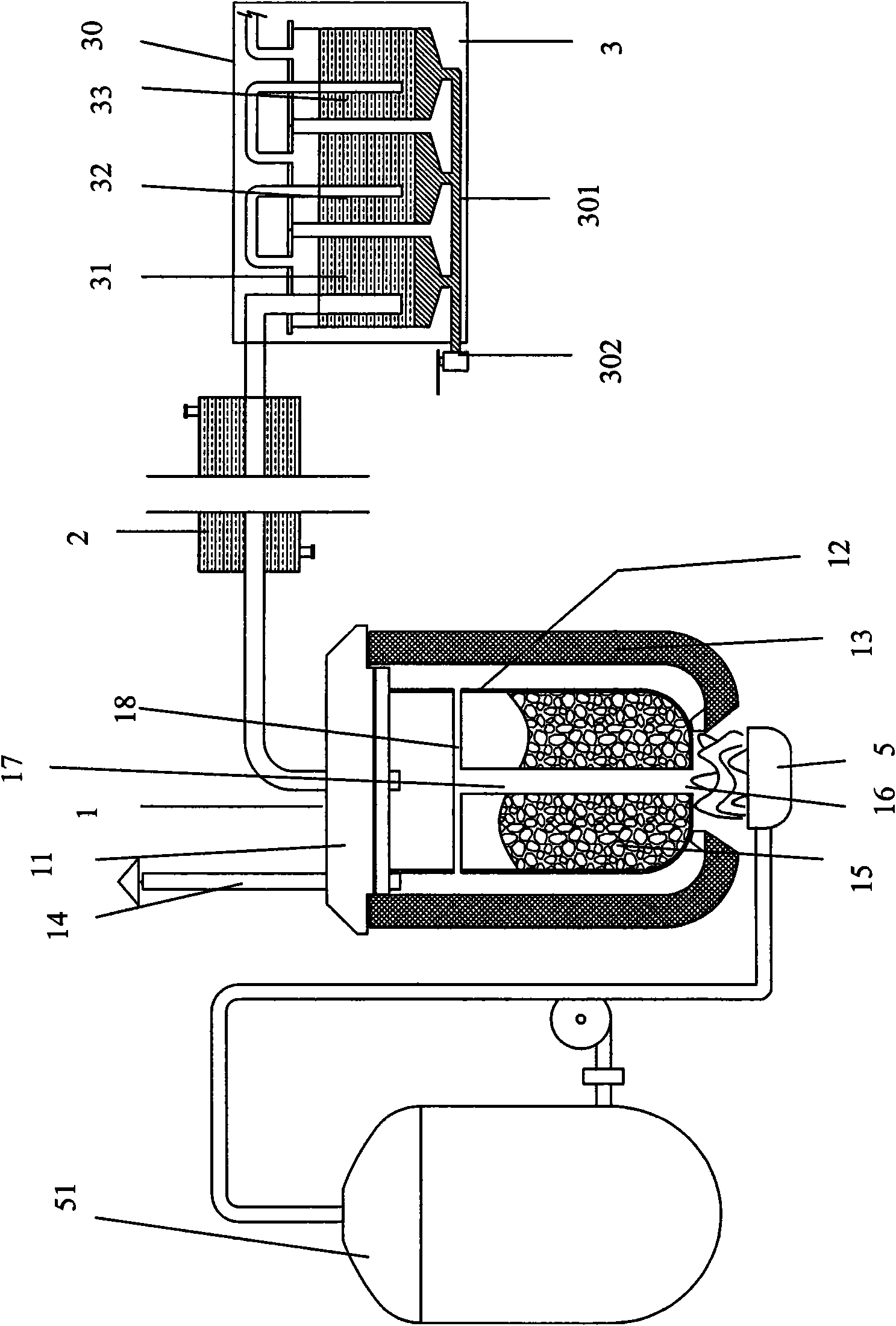
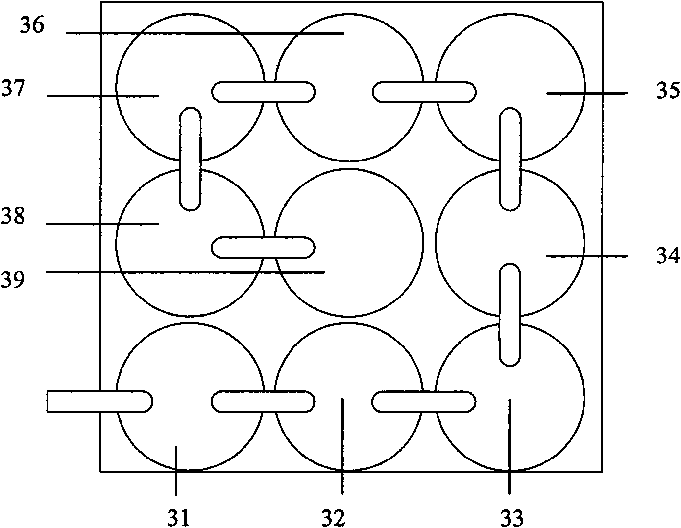
[0030] A kind of FRP pyrolysis recovery device, such as figure 1 , figure 2 , image 3 As shown, it includes a reactor 1, a heating device 5, and an oil-gas separation device 3; the reactor 1 includes a main body 12, a cover body 11 covered on the main body 12, and the outside of the reactor is provided with an insulating layer 13 made of an insulating material for heat preservation. The cavity insulation chamber formed between the layer 13 and the wall of the reactor 1, the reactor main body 12 and the cover body 11 are covered to form an airtight packing chamber 15, the bottom of the main body 12 is provided with a heat hole 16, and the side The wall is symmetrically provided with three heat passage holes 16, and the main body 12 is provided with a main heat passage pipe 17 from the bottom. The outlet ends of each branch heat pipe 18 are connected with three heat passage holes 16 on the side wall, and the heat passage holes 16 on the side wall are communicated through the...
Embodiment 2
[0039] A kind of FRP pyrolysis recovery device, such as Figure 4 As shown, its reactor 1 and heating device 5 are the same as those in Embodiment 1, so they are not repeated here. The main difference is that the oil-gas separation device can be composed of several condensation towers 31 and an oil-liquid separation pool 32. The condensation tower is equipped with an inlet pipe near the bottom and an outlet pipe at the top. Each condensation tower passes through the inlet pipe and the outlet pipe in turn. Connected, the reaction kettle 1 is connected to the inlet pipe of the first condensation tower through the ventilation pipe; the bottom of each condensation tower 31 is provided with a liquid outlet, and the liquid outlet of the condensation tower 31 is connected to the oil separation tank through pipelines 32. The oil-liquid separation tank 32 is a sealed container with a liquid outlet at the bottom and a control valve 33 at the liquid outlet.
[0040] The main difference...
Embodiment 3
[0043] A kind of glass fiber reinforced plastics pyrolysis recovery device, its difference with embodiment one only lies in the structure of reactor 1, as Figure 5 As shown, the reaction kettle 1 comprises a main body 12, a cover body 11 covered on the main body 12, and the outside of the reaction kettle is provided with an insulating layer 13 made of an insulating material, and the space formed between the insulating layer 13 and the wall of the reaction kettle 1 Cavity insulation chamber, the main body 12 is divided into material chamber 151 and fuel chamber 152 again, and this fuel chamber 152 upper end opening, material chamber 151 has a bottom plate, can utilize flange or other joints to assemble between the two, in addition, fuel chamber 152 is connected with a gas pipe connected to the heating device, and the gas pipe is provided with a control valve to adjust the flow of gas; thus, the gas supply device and the reactor 1 share a heat source, and the fuel required by th...
PUM
 Abstract
Description
Claims
Application Information
 - R&D
- Intellectual Property
- Life Sciences
- Materials
- Tech Scout
- Unparalleled Data Quality
- Higher Quality Content
- 60% Fewer Hallucinations
Browse by: Latest US Patents, China's latest patents, Technical Efficacy Thesaurus, Application Domain, Technology Topic, Popular Technical Reports.
© 2025 PatSnap. All rights reserved.Legal|Privacy policy|Modern Slavery Act Transparency Statement|Sitemap|About US| Contact US: help@patsnap.com


