
Image analysis method of biological detector

A technology of image analysis and biological detection, which is applied in the field of image analysis of biological detectors, and can solve problems such as image noise, time-consuming and long-term scanning, optical detection device mechanism and complex procedures, etc.

Inactive Publication Date: 2009-12-02
KAIWOOD TECH
View PDF1 Cites 11 Cited by
  • Summary
  • Abstract
  • Description
  • Claims
  • Application Information

AI Technical Summary

Problems solved by technology

[0005] As mentioned above, the optical detection device has the same technical problem: since the optical scanning method during detection is a continuous and single-point two-dimensional mobile scanning, it takes time to scan for a long time
[0007] However, in the optical detection device, since the optical scanning method during detection is still a continuous linear one-dimensional moving scanning, it still needs time-consuming scanning for a long time, so as to complete the step-by-step capture of each component with the help of one-dimensional moving. Multiple images of multiple inspection points
Furthermore, the array detection sample still needs to be fixed on the base, and with the help of the movement of the one-dimensional mobile platform, only the number of movements is reduced, but the image obtained by scanning after each movement will still produce position deviation , so it is necessary to continuously correct the image positioning, otherwise the accuracy of the detection results cannot be guaranteed
Furthermore, constantly moving the array detection sample may not only cause image noise due to shaking, but may even cause sample damage
The above factors cause the problem that the optical detection device still has complex mechanisms and procedures

Method used


Image

  • Image analysis method of biological detector
  • Image analysis method of biological detector
  • Image analysis method of biological detector

Examples


Embodiment Construction

[0030] In order to make the purpose, features and advantages of the present invention more comprehensible, preferred embodiments of the present invention will be enumerated below and described in detail in conjunction with the accompanying drawings.

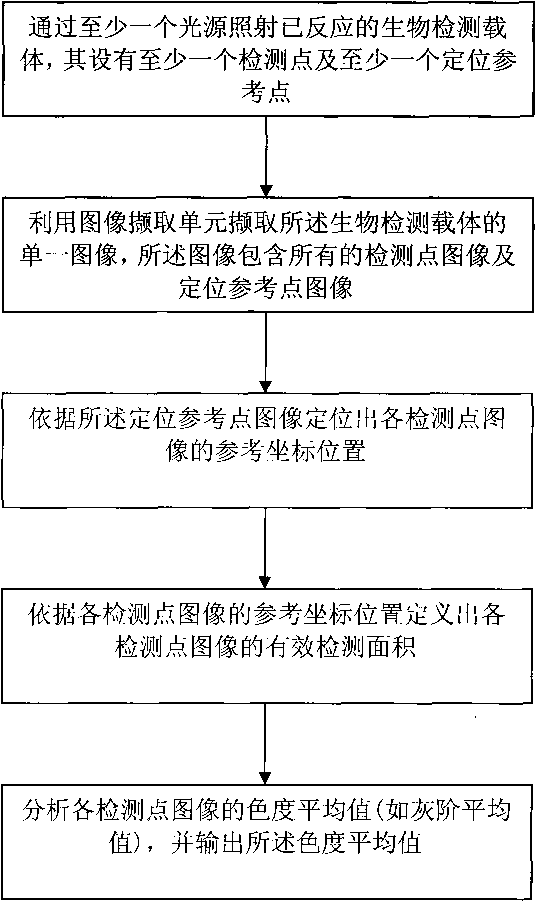
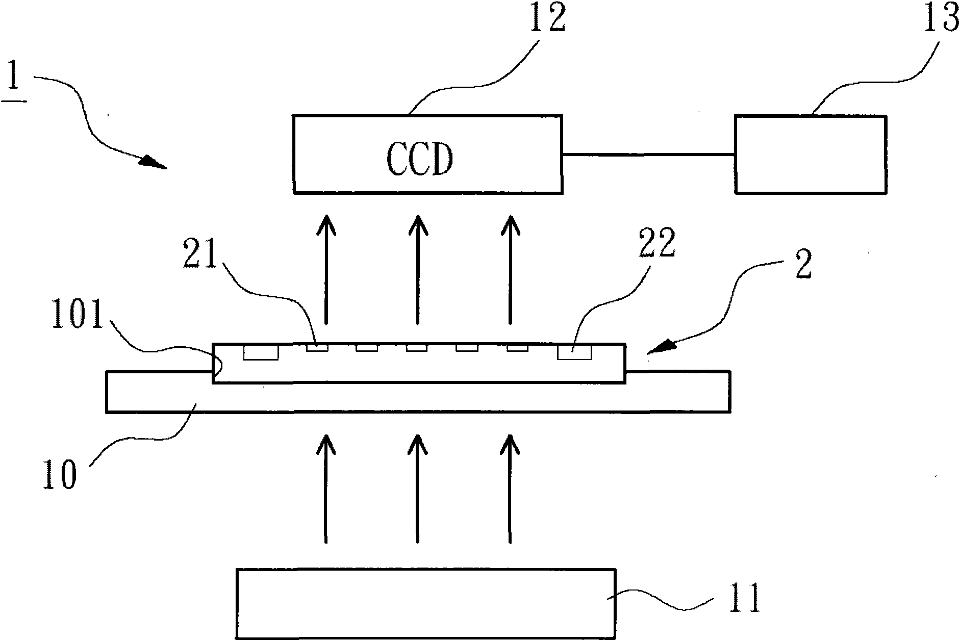
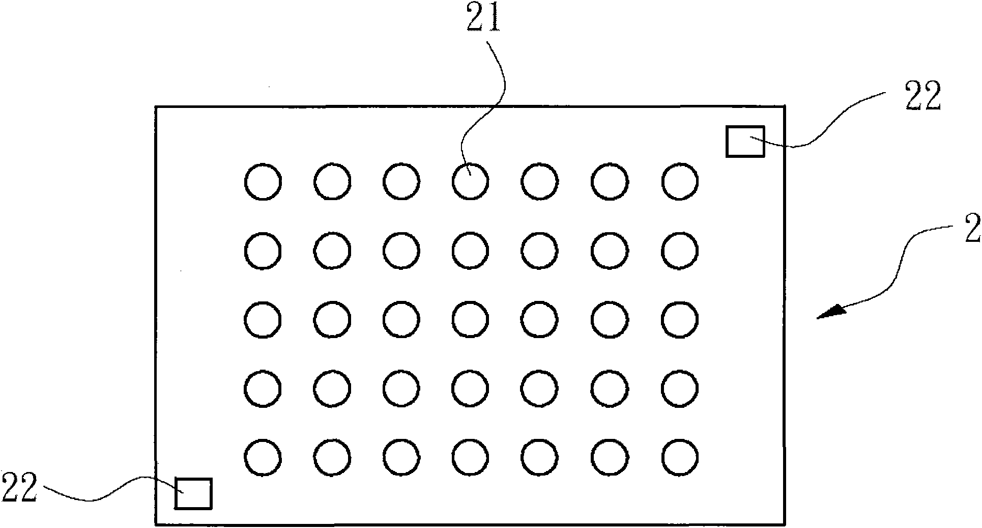
[0031] Please refer to figure 1 , 2 , 3 and 4, the image analysis method of the biological detector of the present invention mainly includes the following steps: irradiating the reacted biological detection carrier 2 with at least one light source 11, which is provided with at least one detection point 21 and at least one positioning reference point 22: Use the image capture unit 12 to capture a single image 3 of the biological detection carrier 2, the image 3 including all detection point images 31 and positioning reference point images 32; according to the positioning reference point images 32, locate each The reference coordinate position 311 of detection point image 31; Define the effective detection area of ​​each detection...


PUM


Abstract

The invention provides an image analysis method of a biological detector, which comprises the following steps: at least one detection point and at least one locate reference point are arranged in the biological detector by a reactive biological detection carrier irradiated by at least one light source; a single image of the biological detection carrier is captured by an image capturing unit, the image contains all detection point images and locate reference point images; the position of the reference coordinate of each detection point image is located according to the locate reference point images; the effective detection area of each detection point image is defined according to the position of the reference coordinate of each detection point image; the chroma average of each detection point image, for example, the gray scale average, is analyzed, and the chroma average is output.

Description

technical field [0001] The present invention relates to an image analysis method for a biological detector, in particular to an image of a biological detector that captures a single image of a biological detection carrier and directly performs image positioning and image chromaticity analysis to facilitate rapid output of detection data Analytical method. Background technique [0002] Biochip (biochip) is a micro-area, high-density detection and analysis tool in biological sciences. Depending on the type or purpose of the biochip, various detection methods can be designed using different principles such as molecular biology, analytical chemistry, and biochemical reactions. analysis mode. Therefore, in medical or biochemical detection, biochips have great application potential and value. Furthermore, different biochips may choose different bio-related molecules (such as genes, proteins, organic compounds or cell tissues, etc.) as detection probes, and may choose to use micr...

Claims


Application Information

Patent Timeline
Patent Type & Authority Applications(China)
IPC IPC(8): G01N33/48G01N21/84G01N21/78
Inventor 庄琮凯吴自强王建华
Owner KAIWOOD TECH
Learn More