Steel wire drawing and releasing automatic tracing and controlling method and device for multi-wire cutting machine

A technology of multi-wire cutting machine and pay-off device, which is applied to fine working devices, control using feedback, and manufacturing tools, etc. To promote the application value, increase economic benefits, and improve the effect of machine reliability

Inactive Publication Date: 2009-12-09
XINXIANG HUASHENG TIANLONG CNC EQUIP
View PDF0 Cites 14 Cited by
  • Summary
  • Abstract
  • Description
  • Claims
  • Application Information

AI Technical Summary

Problems solved by technology

In the production process of multi-wire cutting machines cutting hard materials such as monocrystalline silicon and polycrystalline silicon, the receiving and unwinding devices used ordinary gear reduction motors for speed regulation. This kind of motor has slow speed response and poor instantaneous commutation performance. The frequent positive and negative movement of the pulley and the change of angular velocity will often cause the steel wire to not be evenly wound on the wire pulley, which will cause the steel wire on the take-up and pay-off pulley to be arranged in a spindle shape, and even cause the steel wire to break and make silicon Fragments are broken, causing large economic losses

Method used


Image

  • Steel wire drawing and releasing automatic tracing and controlling method and device for multi-wire cutting machine
  • Steel wire drawing and releasing automatic tracing and controlling method and device for multi-wire cutting machine
  • Steel wire drawing and releasing automatic tracing and controlling method and device for multi-wire cutting machine

Examples


Embodiment 1

[0022] Embodiment one: see figure 1 . The automatic tracking method for the steel wire in the automatic take-up and pay-off device of the multi-wire cutting machine of the present invention, the take-up and take-off device respectively adopts a servo motor, a gear and a rack to drive the mobile platform, and two contact wheels are installed on the mobile platform, and the steel wire Passing through the middle of the two contact wheels, the mobile platform drives the steel wire to move in the axial direction of the two wire wheels. The steel wire automatic tracking method of the present invention, by setting two rotary encoders linked with the contact wheels on the mobile platform, the rotary encoder The encoder shaft is connected to the contact wheel, and the output signal of the rotary encoder is connected to a controller through a wire. The position of the wire in the take-up and pay-off device, so that the steel wires are tightly and evenly arranged in the take-up and pay...

Embodiment 2

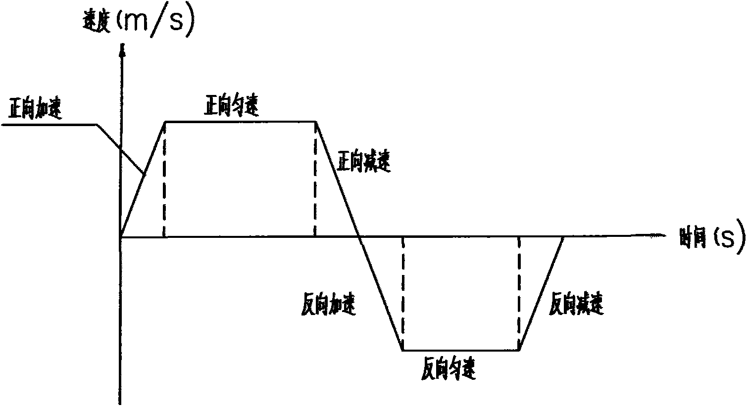
[0025] Embodiment two: see figure 1 . The steel wire automatic tracking method in the automatic receiving and unwinding device of the multi-wire cutting machine in this embodiment is different from the first embodiment in that: the rotary encoder sends an encoded signal and inputs it to the high-speed counter module of the controller, and each channel in the high-speed counter has A flag register, when the CPU processor detects that there is a count value, the flag position of the flag register is set to 1, otherwise it is set to 0, the CPU processor judges the flag bit of the flag register through the programming software, if the value of the flag bit of the flag register is 1, then pass The output module of the program controller sends a forward or reverse signal to control the forward or reverse rotation of the servo motor.

[0026] At the same time, the controller calculates the motion speed V of the servo motor according to the angular velocity ω of the wire wheel and t...

Embodiment 3

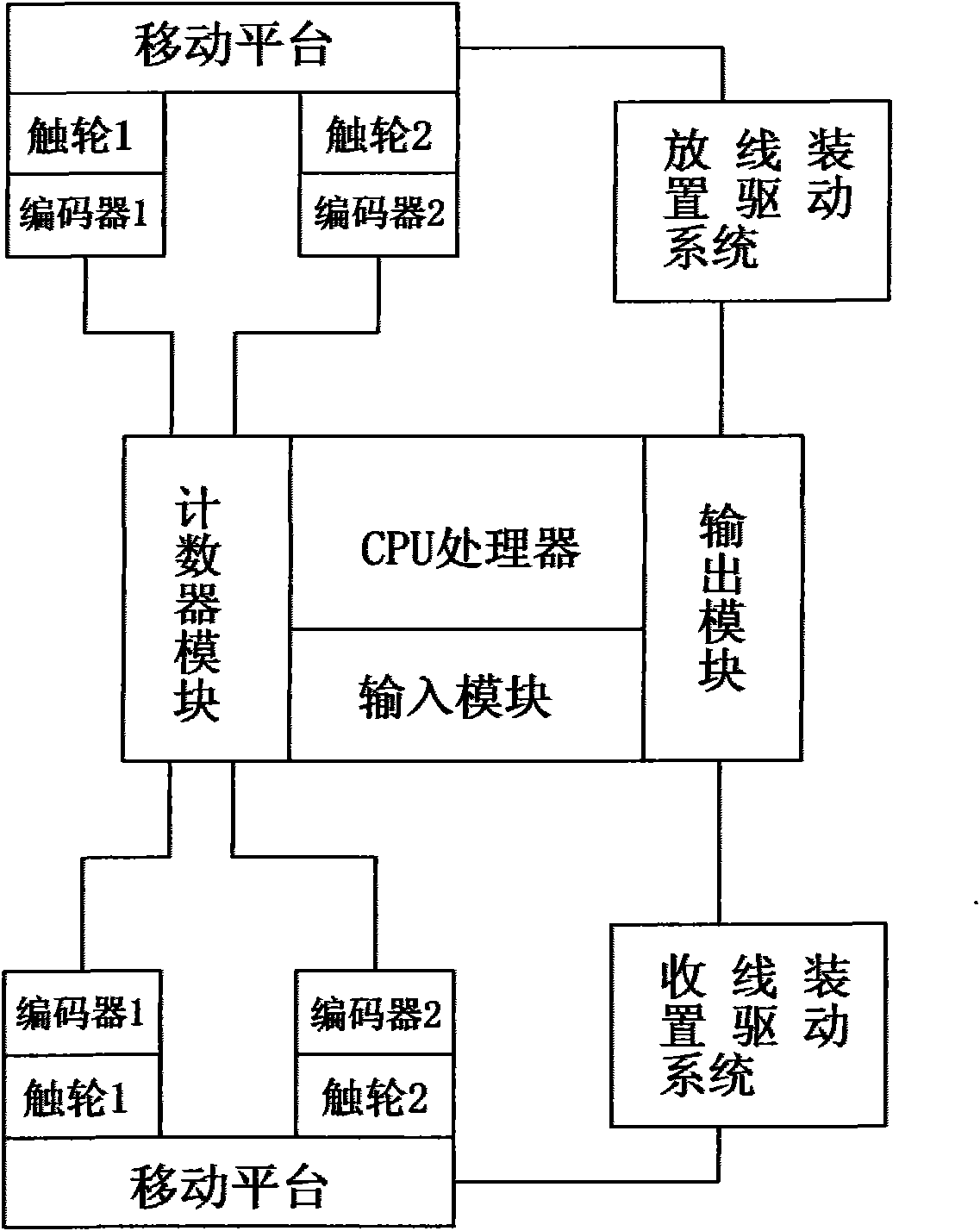
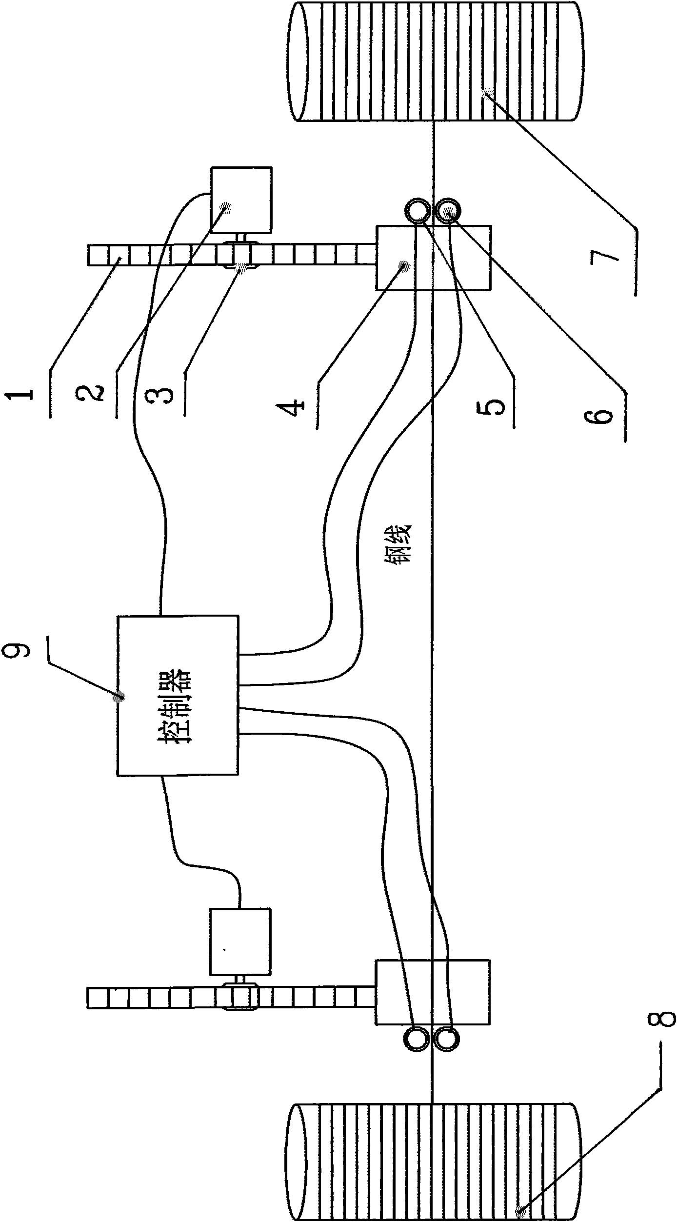
[0027] Embodiment three: see figure 2 . This embodiment is a specific implementation of the multi-wire cutting machine steel wire take-up and pay-off automatic tracking control device, wherein the take-up and pay-off devices all adopt a drive system including a servo motor 2, a gear 3, and a rack 1. Two contact wheels 5 are installed on the mobile platform 4 linked with the rack 1, and a rotary encoder 6 is respectively provided with each contact wheel on the mobile platform, and the coding shaft of the rotary encoder is connected to the contact wheels. , the output signal of each rotary encoder is connected to the controller 9, and the controller 9 controls and connects the servo motor 2. Among the figure, 8 is a pay-off reel, and 7 is a take-up reel.

[0028]The controller of the multi-wire cutting machine steel wire receiving and paying-off automatic tracking control device includes a CPU processor, an input module, an output module, and a high-speed counter module. The ...


PUM


Abstract

The invention relates to a steel wire automatic tracing method and an automatic tracing device in a wire drawing device and a wire releasing device of a multi-wire cutting machine. The automatic wire drawing device and the automatic wire releasing device respectively use a servo motor, a gear rack driving transportation platform, wherein, two trolley wheels are arranged on the transportation platform, and a steel wire passes between the two trolley wheels; the transportation platform are respectively provided with two rotary encoders linking with the two trolley wheels; the rotary encoders are connected with a controller which is connected with the servo motor. The motion direction of the servo motor is determined by the two rotary encoders respectively through the controller so as to automatically correct the position of the steel wire in the wire drawing device and the wire releasing device to ensure that the steel wire is closely and uniformly arranged in the wire drawing device and the wire releasing device. The steel wire drawing and releasing automatic tracing and controlling method and the device for multi-wire cutting machine of the invention can reduce broken wires caused by nonuniform wire drawing and releasing of the wire drawing device and the wire releasing device of the multi-wire cutting machine by more than 95%, which increases the reliability of the machine and ensures the cutting quality of the multi-wire cutting machine for hard materials, such as monocrystalline silicon, polycrystalline silicon and the like, so that the economic benefit is increased.

Description

1. Technical field: [0001] The invention relates to a steel wire tracking control method in a multi-wire cutting machine take-up and pay-off device, in particular to a steel wire automatic tracking method in a multi-wire cutting machine take-up and pay-off device and an automatic tracking device for realizing the method. 2. Background technology: [0002] Multi-wire cutting machine is a kind of machine that uses thin steel wire to cut hard materials such as monocrystalline silicon and polycrystalline silicon. During the cutting process, the steel wire periodically reciprocates at high speed, and there is an acceleration and deceleration process. Each wire wheel must perform a wire take-up and pay-off process within a cycle. Since the diameters of the take-up and pay-off wheels change, the take-up 1. The angular velocity of the pay-off reel also changes, so it is necessary to ensure that the steel wires are evenly arranged on the take-up and pay-off reel. [0003] see image...

Claims


Application Information

Patent Timeline
Patent Type & Authority Applications(China)
IPC IPC(8): B28D5/04G05D3/12G05D3/20
Inventor 孟红军胡蓬辉张万进倪永帅
Owner XINXIANG HUASHENG TIANLONG CNC EQUIP
Why Eureka
Try Eureka