Integrated microfluidic chip and application thereof in living cell control and analysis
A microfluidic chip and cell technology, which is used in tissue cell/virus culture devices, microorganism measurement/inspection, biochemical instruments, etc., to achieve good biocompatibility and excellent light transmittance.
- Summary
- Abstract
- Description
- Claims
- Application Information
AI Technical Summary
Problems solved by technology
Method used
Image
Examples
Embodiment 1
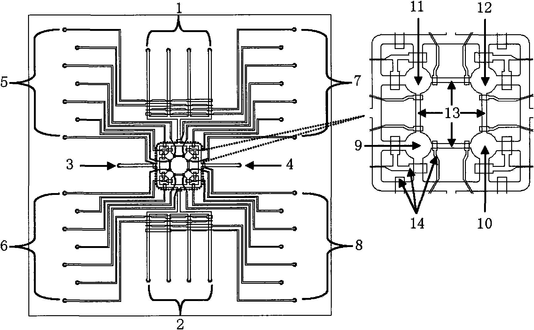
[0024] Such as figure 1 As shown, the integrated microfluidic chip prepared in this example is composed of three layers: a flow layer, a control layer and a cover layer (from top to bottom). Among them, there are eight sample inlets (such as figure 1 and 2, each with 4) and two sample outlets (such as figure 3 and 4) around the fluidized layer, and there are four circular cells in the middle. For the culture chambers (such as figure numbers 9, 10, 11, 12), the adjacent chambers are connected two by two by thin pipes 13 for cell interaction research.
[0025] The control layer is provided with a total of 28 air inlets (such as number 5, 6, 7, and 8, each with 7), which are respectively connected to the closed microvalve switch at the end of a single pipeline.
[0026] Production of microfluidic chips (taking the production of PDMS microfluidic chips as an example):
[0027] 1. Using soft lithography technology to prepare the chip mold, first make the design structure of the f...
Embodiment 2
[0030] The control of the microvalve switch on the air inlet of the control layer to the flow layer pipeline is as follows: figure 2 As shown, when the air inlet 24 does not take in air, the microvalve switch pipeline 23 is in the state of atmospheric pressure, and the microvalve switch 22 is in a closed state. At this time, the fluidized layer pipeline 21 is unblocked, and the samples in the pipeline can enter and exit at will; when the lower pressure (20psi) when the gas 32 enters the microvalve switch pipeline ( image 3 As shown), the microvalve switch 31 expands and presents a protrusion, so that the fluidized layer pipeline is in a half-closed state; further, as Figure 4 As shown, when the higher pressure (40psi) gas 42 enters the microvalve switch pipeline, the microvalve switch 41 is completely close to the fluidized layer pipeline, sealing the fluidized layer pipeline, thereby achieving the purpose of controlling the entry and exit of samples in the fluidized layer ...
Embodiment 3
[0032] This embodiment takes the localized culture of liver cancer cells and fibroblasts in a microfluidic chip as an example.
[0033] 1. First, the microfluidic chip prepared in Example 1 is autoclaved, and then the fluidized layer pipeline and cavity are cleaned (use a micro-syringe pump to inject samples, and the cleaning solution is 0.01M PBS, pH=7.4, flow rate 25μL / min, time 15min), and then coat and modify the surface of the flow layer pipe and cavity (coating modifier is poly-L-lysine, 100μg / mL, 37°C, 2h), and then wash (Sampling is also injected using a micro-syringe pump, 0.01M PBS is selected as the cleaning solution, pH=7.4, the flow rate is 25 μL / min, and the time is 15 min), blow dry with sterile gas, and set aside.
[0034] 2. Preparation of liver cancer cells and fibroblast suspensions. In this example, liver cancer cell line cells (HepG2 cells) and fibroblast cell line cells (NIH 3T3 cells) were selected, and the number of cells was amplified by conventional i...
PUM
| Property | Measurement | Unit |
|---|---|---|
| thickness | aaaaa | aaaaa |
Abstract
Description
Claims
Application Information
 - R&D
- Intellectual Property
- Life Sciences
- Materials
- Tech Scout
- Unparalleled Data Quality
- Higher Quality Content
- 60% Fewer Hallucinations
Browse by: Latest US Patents, China's latest patents, Technical Efficacy Thesaurus, Application Domain, Technology Topic, Popular Technical Reports.
© 2025 PatSnap. All rights reserved.Legal|Privacy policy|Modern Slavery Act Transparency Statement|Sitemap|About US| Contact US: help@patsnap.com


