
Secondary splitter blade type centrifugal impeller

A technology of splitter blades and centrifugal impellers, which is applied to non-variable pumps, parts of pumping devices for elastic fluids, machines/engines, etc., can solve problems such as weak boosting capacity and narrow stable operating range, and achieve Effects of improving flow conditions, increasing flow efficiency, and expanding stable operation range

Inactive Publication Date: 2009-12-09
XI AN JIAOTONG UNIV
View PDF0 Cites 25 Cited by
  • Summary
  • Abstract
  • Description
  • Claims
  • Application Information

AI Technical Summary

Problems solved by technology

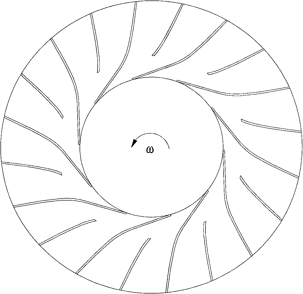
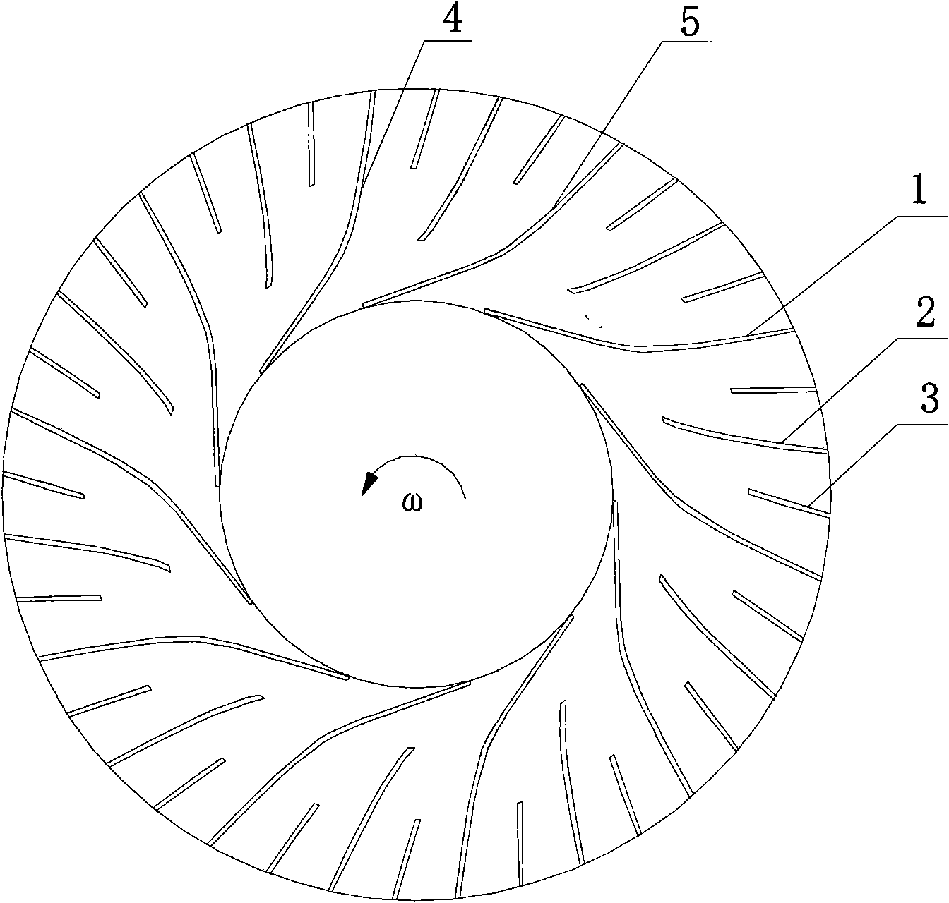
[0004] In order to solve the problems of narrow stable operation range and weak pressurization capacity of the primary splitter vane centrifugal impeller at high speed, the present invention provides a secondary splitter vane centrifugal impeller

Method used

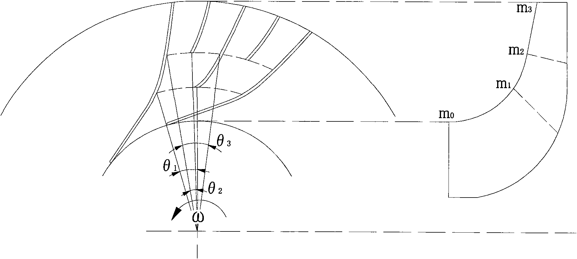

Image

  • Secondary splitter blade type centrifugal impeller
  • Secondary splitter blade type centrifugal impeller
  • Secondary splitter blade type centrifugal impeller

Examples


Embodiment 1

[0024] Example 1: When the first splitter vane meridian relative to the inlet position m 1 =0.1, the meridional direction of the second splitter vane relative to the inlet position m 2 =0.5, the circumferential relative inlet position of the first splitter vane θ 1 =0.5, the circumferential relative inlet position of the second splitter vane θ 2 0.5 on the wheel side and 0.5 on the wheel cover side;

Embodiment 2

[0025] Embodiment 2: When the meridional direction of the first splitter blade is relative to the inlet position m 1 =0.2, the meridional direction of the second splitter vane relative to the inlet position m 2 =0.6, the circumferential relative inlet position of the first splitter vane θ 1 =0.45, the position of the second splitter blade relative to the inlet in the circumferential direction θ 2 0.45 on the wheel side and 0.55 on the wheel cover side;

Embodiment 3

[0026] Embodiment 3: When the meridional direction of the first splitter blade is relative to the inlet position m 1 =0.3, the meridional direction of the second splitter vane relative to the inlet position m 2 =0.7, the circumferential relative inlet position of the first splitter vane θ 1 =0.4, the position of the second splitter blade relative to the inlet in the circumferential direction θ 2 0.4 on the wheel side and 0.6 on the wheel cap side.


PUM


Abstract

The invention discloses a secondary splitter blade type centrifugal impeller, comprising a long blade extending from impeller inlet to impeller outlet. The suction surface of the long blade and the pressure surface of an adjacent long blade form a complete air flow passage; wherein a middle blade is arranged between the two long blades to form a primary splitter blade; the two sides of the middle blade are respectively provided with a short blade to form a secondary splitter blade; the inlet of the middle blade deflects toward the suction surface in the air flow passage; the inlet at the wheel disc side of the short blade deflects towards the suction surface in the air flow passage, and the inlet at the wheel cap of the short blade deflects towards one side of the pressure surface in the air flow passage; the number ratio of the long, middle and short blades is 1:1:2; and the long, middle and short blades are evenly distributed at the periphery of the outlet of the impeller. The centrifugal impeller of the invention gradually increases splitter blades, and can effectively allocate blade passage gas flow and blade aerodynamic load, improve flow uniformity at the impeller outlet and improve pressurizing capacity and steady operation range of the centrifugal impeller.

Description

technical field [0001] The invention relates to a centrifugal impeller, in particular to a secondary splitter vane type centrifugal impeller. Background technique [0002] Centrifugal compressors play an important role in various sectors of the national economy, especially in metallurgy, petrochemical, natural gas transmission, refrigeration, and power industries. In recent years, advanced centrifugal compressor technology is developing towards high speed, high pressure ratio, and high efficiency, which puts forward higher requirements for the design of centrifugal compressors. As the main part of the centrifugal compressor, the centrifugal impeller converts the mechanical energy of the rotating shaft into the pressure energy and kinetic energy of the gas through the centrifugal force; and in the high-speed centrifugal impeller, the air flow is more affected by the reverse pressure gradient and viscosity. Unstable flow phenomena such as flow separation, surge, and blockage ...

Claims


Application Information

Patent Timeline
Patent Type & Authority Applications(China)
IPC IPC(8): F04D29/22F04D29/24
Inventor 张楚华袁丹妮
Owner XI AN JIAOTONG UNIV
Learn More