Method for manufacturing motor rotor and self-aligning positioning mechanism used thereby

A technology of motor rotor and manufacturing method, which is applied in the field of automatic centering positioning mechanism, can solve the problems of reducing the adhesive force of adhesives, reducing the adhesive force between the mandrel and magnetic steel, and high maintenance costs of machine tools, so as to avoid bonding agent aging, improve production accuracy, and improve production efficiency

Active Publication Date: 2009-12-09
NINGBO YUNSHENG +3
View PDF0 Cites 9 Cited by
  • Summary
  • Abstract
  • Description
  • Claims
  • Application Information

AI Technical Summary

Problems solved by technology

The defect of this production method is that the coaxiality processing adopted requires quite high precision of the machine tool, and special machine tools must be used for processing to meet the coaxiality requirements of the product, and the maintenance cost of the machine tool is very high, otherwise the precision of the machine tool A slight change will directly affect the production accuracy of the product; secondly, due to the high requirements of the coaxial processing process, the resulting scrap rate is high, which will eventually greatly reduce the production efficiency of the product and greatly increase the production cost of the product; this kind of manufacturing Another defect of the method is that: since the magnetic steel and the mandrel are assembled and electroplated as a whole, it is inconvenient, and it is easy to cause the coating to fall off due to weak combination at the junction of the magnetic steel and the mandrel; this manufacturing method also has a The defect is that: during the machining process of the machine tool, due to the penetration of cutting oil and the reaction with the adhesive, the adhesion between the mandrel and the magnetic steel is reduced; at the same time, during the overall coating process, the harsh environment of the plating solution produces The aging of the adhesive will eventually reduce the adhesive force of the adhesive

Method used


Image

  • Method for manufacturing motor rotor and self-aligning positioning mechanism used thereby
  • Method for manufacturing motor rotor and self-aligning positioning mechanism used thereby
  • Method for manufacturing motor rotor and self-aligning positioning mechanism used thereby

Examples


Embodiment Construction

[0021] The present invention will be further described below in conjunction with accompanying drawing and embodiment:

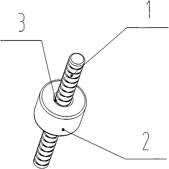
[0022] Such as image 3 As shown, the motor rotor 3 includes a mandrel 1 and a magnetic steel 2 fixed on the outer surface of the mandrel 1, and the mandrel 1 is directly bonded and fixed to the inner surface of the magnetic steel 2 by an adhesive.

[0023] The above motor rotor is manufactured by the following method:

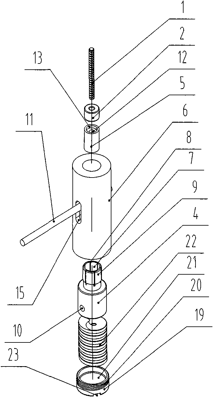
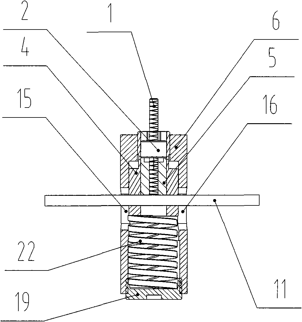
[0024] Such as figure 1 , figure 2 Shown is the automatic centering positioning mechanism used for assembling the motor rotor, which is composed of the centering rod 4, the positioning column 5, the jacket 6, the pressure rod 11, the spring 22 and the adjustment rod 19.

[0025] Such as Figure 4 As shown, the self-aligning rod 4 has a through hole 7, which is a clearance fit with the outer diameter of the positioning column 5. The upper part of the self-aligning rod 4 is surrounded by a groove 8, and the outer surface 9 corresponding to...


PUM


Abstract

The invention provides a method for manufacturing a motor rotor and a self-aligning positioning mechanism used thereby. The method for manufacturing the motor rotor is characterized in that the motor rotor is formed by splicing a mandrel and magnetic steel by the self-aligning positioning mechanism through binding agent. The self-aligning positioning mechanism consists of a locating column, an aligning rod, an outer sleeve, a spring and a regulating rod, wherein the locating column contains a locating hole, communicating grooves are arranged around the upper part of the aligning rod, the side of the aligning rod at the communicating grooves is a reversed-V-shaped conical surface which is matched with a corresponding reversed-V-shaped conical surface at the upper part of an inner cavity of the outer sleeve, and the lower part of the aligning rod is provided with a transverse through hole that is in clearance fit with a pressure bar; the outer sleeve is provided with an inner hole which is in clearance fit with the aligning rod, the two sides of the outer sleeve are symmetrically provided with two long grooves, the pressure bar is inserted into the inner hole of the aligning rod and can move up and down inside the two long grooves, the lower part of the outer sleeve is matched with the regulating rod by screw thread, and the spring is arranged between the aligning rod and the regulating rod. The invention has the advantages of greatly improving the accuracy of product and manufacturing efficiency as well as reducing the manufacturing cost of the product.

Description

technical field [0001] The invention relates to a manufacturing method of a motor rotor, in particular to a permanent magnet rotor applied to a high-speed motor, and also relates to an automatic centering positioning mechanism used in the manufacturing. Background technique [0002] With the continuous improvement and improvement of the performance of permanent magnet materials, the development and application of permanent magnet motors have entered a new stage, and are currently developing in the direction of high power (ultra-high speed). The production requirements of the permanent magnet precision motor rotor working in a high-speed environment are getting higher and higher. [0003] Existing motor rotors include magnets and mandrels. The magnets used are directly connected to the mandrel with adhesives without any surface treatment. After the magnets and mandrel are assembled, they must be simultaneously Axial processing to finally meet the precision requirements of th...

Claims


Application Information

Patent Timeline
Patent Type & Authority Applications(China)
IPC IPC(8): H02K15/02H02K1/22B23Q3/00
Inventor 阚荣许光雷
Owner NINGBO YUNSHENG
Why Eureka
Try Eureka