
Resonant intake tube of natural gas engine

A technology of engine and natural gas, applied in the field of resonant intake pipe structure of natural gas engine, can solve the problems affecting the working stability, economy and emission performance of the engine, gas pressure fluctuation phenomenon, combustion process difference, etc.

Inactive Publication Date: 2009-12-23
HARBIN HACHUAN POWER TECH
View PDF0 Cites 8 Cited by
  • Summary
  • Abstract
  • Description
  • Claims
  • Application Information

AI Technical Summary

Problems solved by technology

In the intake pipe of a four-stroke engine, the periodic opening and closing of the intake valve and the reciprocating motion of the piston make the gas in the intake pipe intermittently flow, and at the same time produce strong gas pressure fluctuations. A pressure fluctuation with a certain amplitude will be generated. This pressure wave propagates along the intake pipe at the speed of sound, and reciprocates between the opening end of the intake pipe and the intake valve. If the structure of the intake system can be reasonably designed, the next cycle of intake air will Just before the door closes, there is a positive pressure peak returning to the intake valve, then more gas can be pushed into the cylinder to achieve the effect of supercharging, but due to the different flow losses and pressure fluctuation effects in the intake pipe of each cylinder, the There are differences in the amount of air entering each cylinder, the mixture of air and fuel in each cylinder is different, and the organization of the combustion process is also different, which will cause differences in the combustion process of each cylinder and directly affect the working stability, economy and emission performance of the engine.

Method used


Image

  • Resonant intake tube of natural gas engine
  • Resonant intake tube of natural gas engine
  • Resonant intake tube of natural gas engine

Examples


Embodiment Construction

[0017] The present invention is described in more detail below in conjunction with accompanying drawing example:

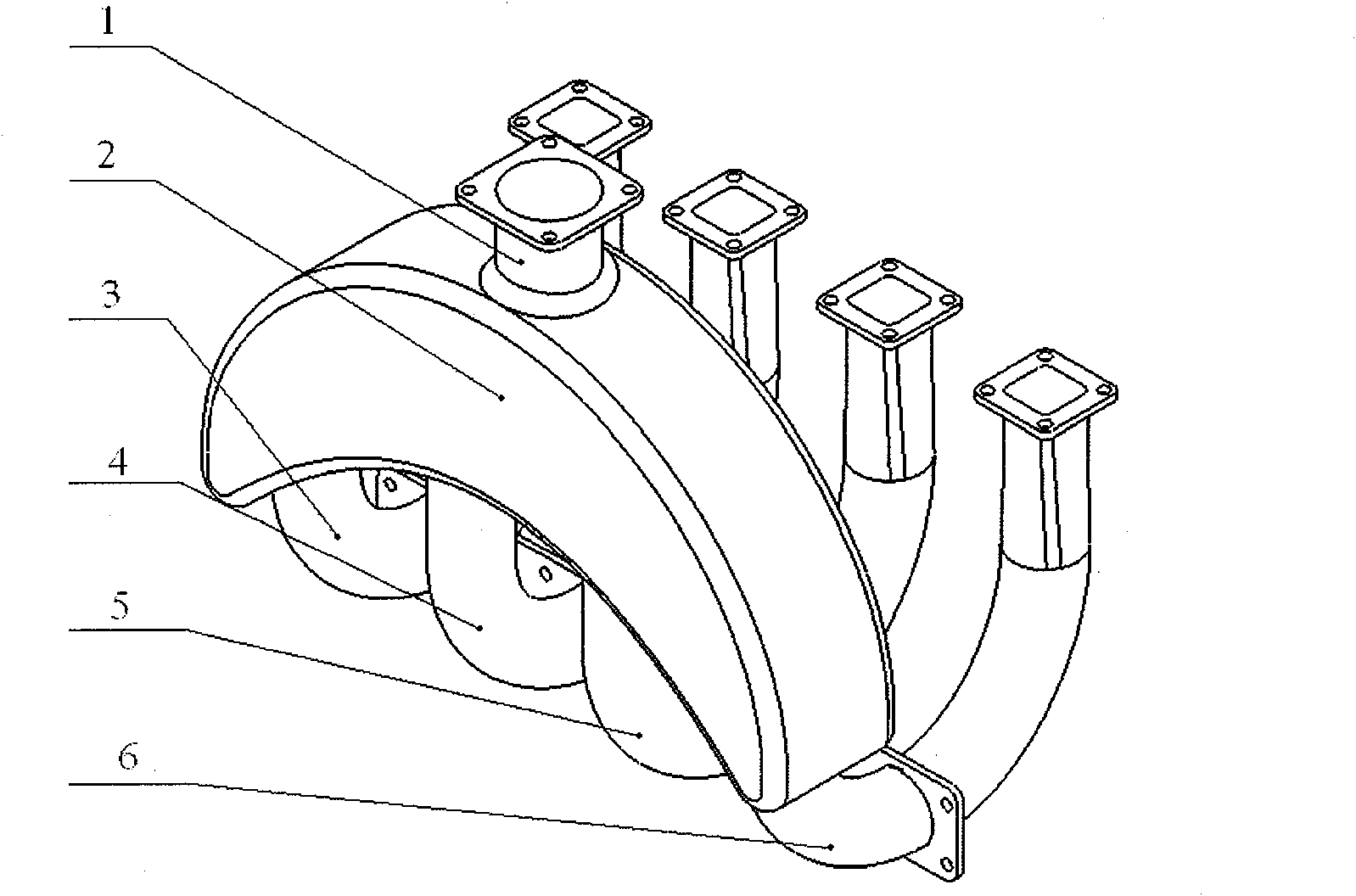
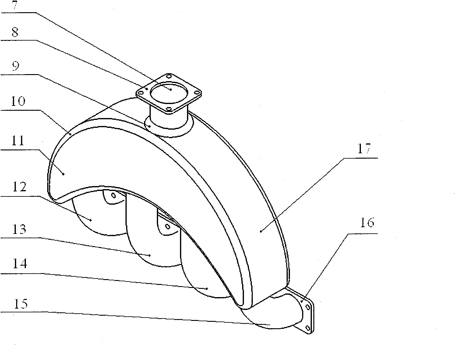
[0018] A resonant intake pipe for a natural gas engine is composed of an intake manifold, a resonant cavity and an intake manifold. The length of the intake manifold is 50mm, and the inner diameter is 60mm. The gas main pipe and the resonant cavity are connected by a rounded corner with a radius of 10mm to reduce the energy loss when the air intake main pipe flows to each manifold. The volume of the resonant cavity is 2.5L. A section of arc surface, the entire resonant cavity presents a crescent shape, and the four intake manifolds are symmetrical in pairs along the plane passing through the center line of the intake manifold and perpendicular to the two crescent-shaped sides of the resonant cavity, with short manifold lengths on both sides is 500mm, but the length of the path that the air flows from the inlet of the intake manifold to the outlet of each manifold ...


PUM


Abstract

The invention provides a resonant intake tube of a natural gas engine, comprising a resonant cavity, an intake collector positioned on the upper part of the resonant cavity and intake manifolds positioned on the lower part of the resonant cavity; wherein, the side wall surface of the resonant cavity, which is connected with the intake collector is shaped like a section of arc surface; the whole resonant cavity is crescent; four intake manifolds go along the center line of the intake collector and are pairwise symmetrical with the planes vertical to the two crescent sides of the resonant cavity; the length of the two intake manifolds in the middle is larger than that of the intake manifolds at both sides; the length of path of the air flowing from the entrance of the intake collector to the exit of each intake manifold is equal. The resonant intake tube not only can fully utilize the resonance effect of the intake air to improve the charging efficiency of the engine but also can improve the unevenness of the intake air of the natural gas engine.

Description

(1) Technical field [0001] The invention relates to the technical field of engines, in particular to a natural gas engine resonant intake pipe structure. (2) Background technology [0002] The increasingly severe energy shortage and environmental pollution have forced automobile manufacturers to actively research engine energy-saving technologies, develop high-efficiency after-treatment devices, and actively explore petroleum alternative energy sources. Natural gas has become the first choice of alternative energy for vehicles due to its advantages of abundant resources and clean combustion. However, natural gas is a gaseous fuel. When the intake port is used to form a mixture, the gaseous fuel will occupy a certain amount of intake charge volume, reducing the amount of air entering the cylinder. Therefore, the power density of a natural gas engine is usually about 10% lower than that of gasoline engines and diesel engines. . In the intake pipe of a four-stroke engine, the...

Claims


Application Information

Patent Timeline
IPC IPC(8): F02M35/104
Inventor 杨立平马修真李文辉姚崇范立云
Owner HARBIN HACHUAN POWER TECH
Learn More