

Faucet
A faucet and valve plate technology, applied in the faucet field, can solve the problems of time-consuming deposition, high deposition cost and high equipment cost
- Summary
- Abstract
- Description
- Claims
- Application Information
AI Technical Summary
Problems solved by technology
Method used
Image

Examples
example 1
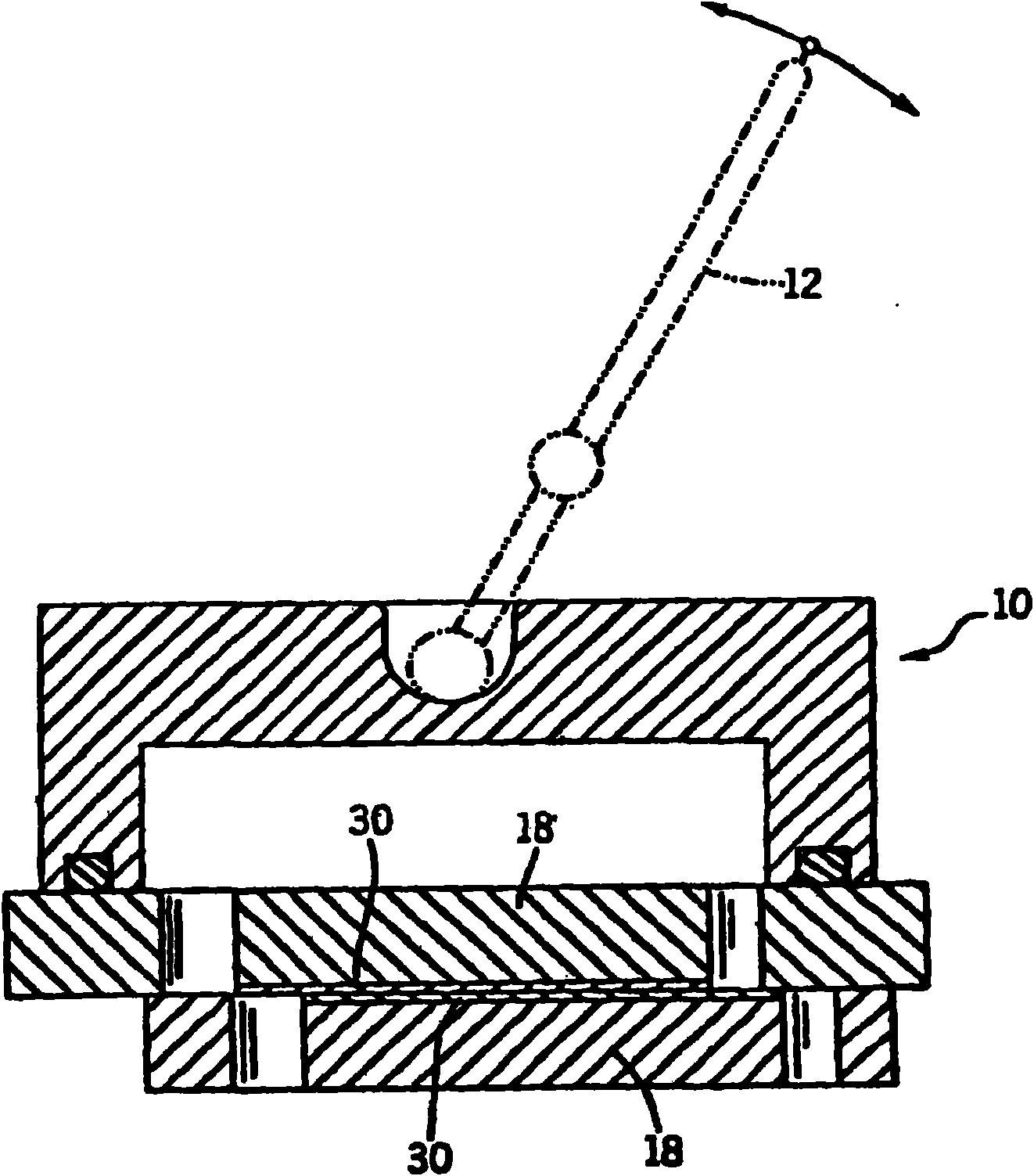
[0042] A pure stainless steel valve disc is placed in a vacuum deposition chamber combined with an arc evaporation cathode and a sputtering cathode. The arc light source is equipped with filtering equipment to reduce the introduction of large particles into the cladding, as described, for example, in US Patent Nos. 5,480,527 and 5,840,163, which are incorporated herein by reference. Argon and nitrogen sources were connected to the chamber through manifolds with adjustable valves to control the flow rate of each gas into the chamber. The sputtering cathode was connected to the negative output of the DC power supply. The anode side of the power supply is connected to the chamber wall. The cathode material is chromium. A valve disc is placed in front of the cathode and can be rotated or moved during deposition to ensure uniform coating thickness. The disks are electrically isolated from the chamber and connected through their mounting brackets to the negative output of the pow...
example 2
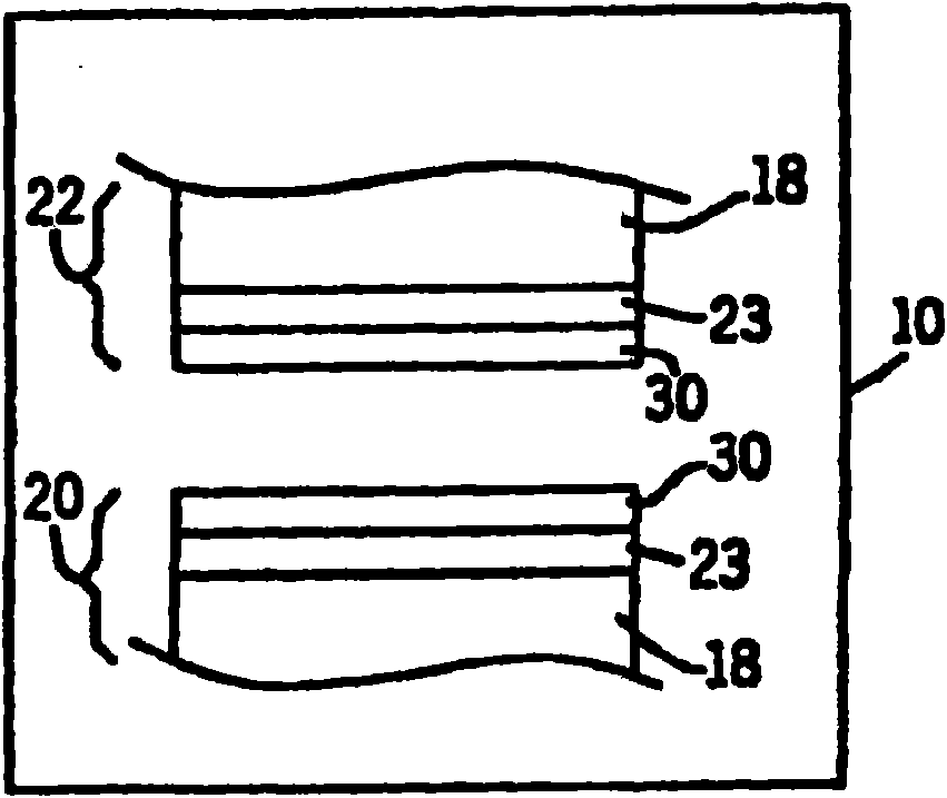
[0048] The clean zirconium valve disc was placed in a hot air oven, heated to a temperature of 560°C, held at this temperature for approximately 6 hours, and then cooled. Thus, a strengthening layer of zirconia is formed on the surface of the substrate, which has a thickness of 5 to 10 micrometers. The disc was then placed in a vacuum deposition chamber incorporating a filtered arc evaporation cathode and a sputtering cathode. An adhesion layer of chromium with a thickness of about 20 nm was deposited on the valve disc by sputtering as described in Example 1. After deposition of the chromium adhesion layer, an amorphous diamond layer was deposited as described in Example 1.
[0049] Valve discs made of zirconium and treated as described to form a multilayer structure on their surface were tested for scratch resistance using a scratch tester with varying loads. Under a load of 3 Newtons, a tip with a radius of 100 micrometers produced scratches approximately 4.7 micrometers d...
example 3
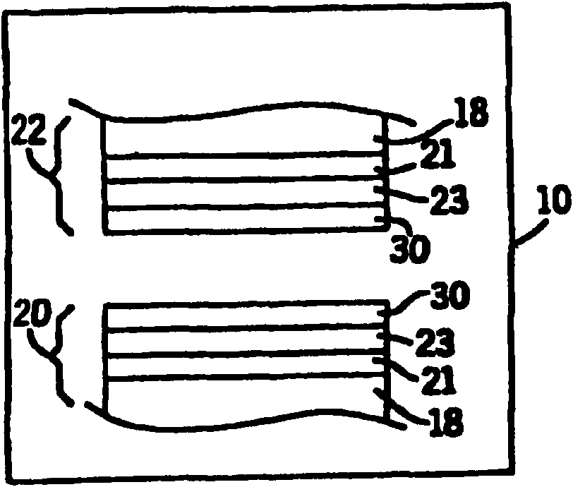
[0051]The purified molded glass disc is placed in a vacuum deposition chamber incorporating a laser ablation source, PECVD source and sputter cathode. The valve disc is subjected to RF (Radio Frequency) discharge plasma cleaning by known equipment. Then, an adhesion layer of titanium with a thickness of about 20 nanometers was deposited on the valve disc by sputtering. Then, a reinforcement layer of DLC with a thickness of about 3 microns was deposited on top of the adhesion layer by PECVD using known deposition parameters. Then, an amorphous diamond layer with a thickness of about 300 nanometers was deposited on top of the DLC layer by laser ablation using typical deposition parameters.
PUM
| Property | Measurement | Unit |
|---|---|---|
| Thickness | aaaaa | aaaaa |
| Thickness | aaaaa | aaaaa |
| Hardness | aaaaa | aaaaa |
Abstract
Description
Claims
Application Information