Brake spacer structure for disc brake

A disc type and pad technology, applied in the field of bicycle brake structure, can solve the problems of insufficient brake pad structure, leakage of brake fluid, brake disc brake failure, etc., and achieve the effect of reducing the risk of brake failure and brake fluid leakage.

Inactive Publication Date: 2009-12-30
ASHIMA LTD
View PDF0 Cites 5 Cited by
  • Summary
  • Abstract
  • Description
  • Claims
  • Application Information

AI Technical Summary

Problems solved by technology

[0004] However, this traditional brake pad is not equipped with a heat-insulating structure or member on the brake sheath to avoid heat generation, and it is impossible to prevent heat from being transmitted to the hydraulic system during braking; therefore, when the disc brake is frequently used After operation, the high temperature generated by it will easily cause the brake disc to fail (brake drag); and the heat generated during the braking process will increase the temperature of the brake fluid in the hydraulic brake, causing the brake fluid to evaporate or the thermal damage of the oil seal to cause brake fluid Leakage, what's more, thermal damage to the oil seal causes poor piston reset and increases the possibility of brake failure; obviously there are deficiencies in the existing brake pad structure

Method used


Image

  • Brake spacer structure for disc brake
  • Brake spacer structure for disc brake
  • Brake spacer structure for disc brake

Examples


Embodiment Construction

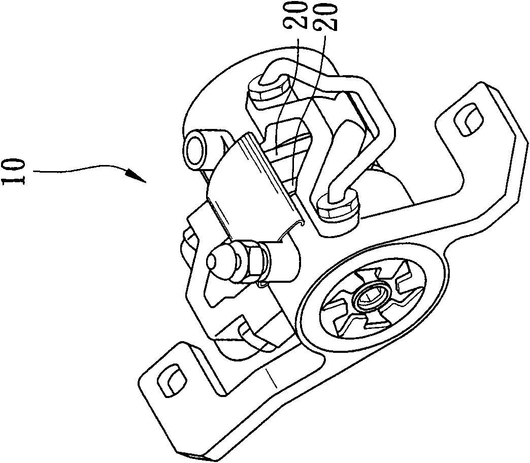
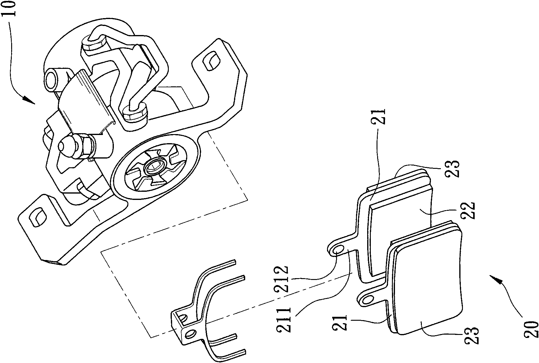
[0027] The present invention relates to a brake pad structure for disc brakes, please refer to Figure 1 to Figure 2 As shown, a hydraulic disc brake 10 is suitable for being installed on a fork pipe (not shown in the figure), and is used to brake a brake disc (not shown) that operates synchronously with the bicycle wheel. The brake 10 includes a pair of brake pads 20, the two brake pads 20 are movably installed in the hydraulic disc brake 10 and rub against the brake disc during the braking action;

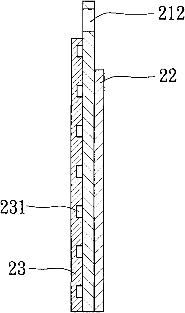
[0028] Any of the brake pads 20 includes a brake sheath 21, the brake sheath 21 is provided with an ear portion 211 extending toward the top, the ear portion 211 is provided with a perforation 212, and a fixing bolt 30 is provided through the ear portion 211. The perforation 212 of the ear portion 211, and the brake pad 20 is installed on the main structure of the hydraulic disc brake 10; thereby, when the hydraulic disc brake 10 operates, the any brake pad 20 is facing The brak...


PUM


Abstract

The invention relates to a brake spacer structure for a disc brake, comprising a brake jacket, a brake liner and a composite board, wherein the brake jacket is arranged in a movable way and suitable for a hydraulic disc brake and comprises a first end surface and a second end surface which is reversed to the first end surface, and the first end surface faces to a brake disc when being assembled; the brake liner is fixedly arranged on the first end surface of the brake jacket and used for rubbing the brake disc during braking action; the composite board is fixedly arranged on the second end surface of the brake jacket and used for providing friction force and mechanical force needed during braking to ensure the brake spacer structure not to be damaged during production, loading or unloading and transportation and when the brake spacer structure is attached to a brake caliper, and can restrain heat energy generation during the braking and reduce heat energy conducted to the brake caliper, a brake fluid and a piston oil seal of the disc brake, and the low heat energy conductivity of the composite board prevents the brake fluid from generating great high temperature so as to prevent brake failure due to the expansion of the brake fluid and brake failure due to brake fluid leakage caused in such a way that the piston oil seal loses elasticity due to the evaporation or the high temperature of the brake fluid.

Description

technical field [0001] The invention relates to a bicycle brake structure, in particular to a brake pad structure for disc brakes. Background technique [0002] The brakes of bicycles have undergone continuous evolution, from traditional frame brakes to disc brakes, and further evolved to today's hydraulic disc brakes. As we all know, the braking effect of disc brakes is far better than that of frame brakes, and the mechanical effect of hydraulic control is stronger than that of mechanical control. Therefore, hydraulic brakes are often used for high braking. effect of mountaineering bicycles or off-road bicycles; [0003] Hydraulic disc brakes for bicycles generally have a pair of brake pads, and the existing brake pads are all provided with a brake sheath and a brake lining, and the brake lining is firmly attached to the brake sheath One side of the pair of brake pads, and the two brake linings of the pair of brake pads are opposite to each other. When braking, the two br...

Claims


Application Information

Patent Timeline
Patent Type & Authority Applications(China)
IPC IPC(8): B62L1/02F16D65/092F16D69/02
Inventor 莫韦恩
Owner ASHIMA LTD
Why Eureka
Try Eureka