Heat recovery fresh air unit

A technology of fresh air unit and heat recovery, applied in the directions of space heating and ventilation, space heating and ventilation details, ventilation and heating energy recovery system, etc. It can reduce the risk of secondary pollution, improve work efficiency, and solve the problem of temperature and humidity control.

Inactive Publication Date: 2009-12-30
SUZHOU UNIV
View PDF0 Cites 24 Cited by
  • Summary
  • Abstract
  • Description
  • Claims
  • Application Information

AI Technical Summary

Problems solved by technology

In the past, in order to ensure the temperature and humidity control, the traditional primary return air was often used for reheating. Now, in order to save energy, the secondary return air has to be used, which makes the dew point of the machine to be controlled by the air conditioning unit lower, and the lower the dew point of the machine, the chilled water required The lower the temperature, the lower the efficiency of the refrigerant;
[0006] (2) During the air-conditioning period, as the outdoor temperature drops, in order to ensure the air-conditioning requirements and energy-saving needs of most spaces, the water temperature of the centralized supply of chilled water is often increased, which objectively results in low dehumidification capacity; especially the fresh air dehumidification capacity is low
[0007] (3) In the inner area of ​​a large building, when the outer area of ​​the building does not need cooling (excessive season) or heating (winter), some inner areas still need cooling, so the air conditioning system is best equipped with a four-pipe air-conditioning terminal, but in order to save energy , and only equipped with two-pipe air-conditioning terminal
The indoor coil only plays a cooling role, so the required chilled water temperature is higher
According to the traditional design concept, two chilled water sources with different temperatures are required, so the configuration of the entire refrigeration system is also relatively complicated.
If the concept of fresh air treatment is realized and the humidity handling capacity of the original system is improved to improve indoor air quality, some results have been achieved, but the current fresh air treatment unit cannot meet the indoor temperature and humidity control requirements

Method used


Image

  • Heat recovery fresh air unit

Examples


Embodiment 1

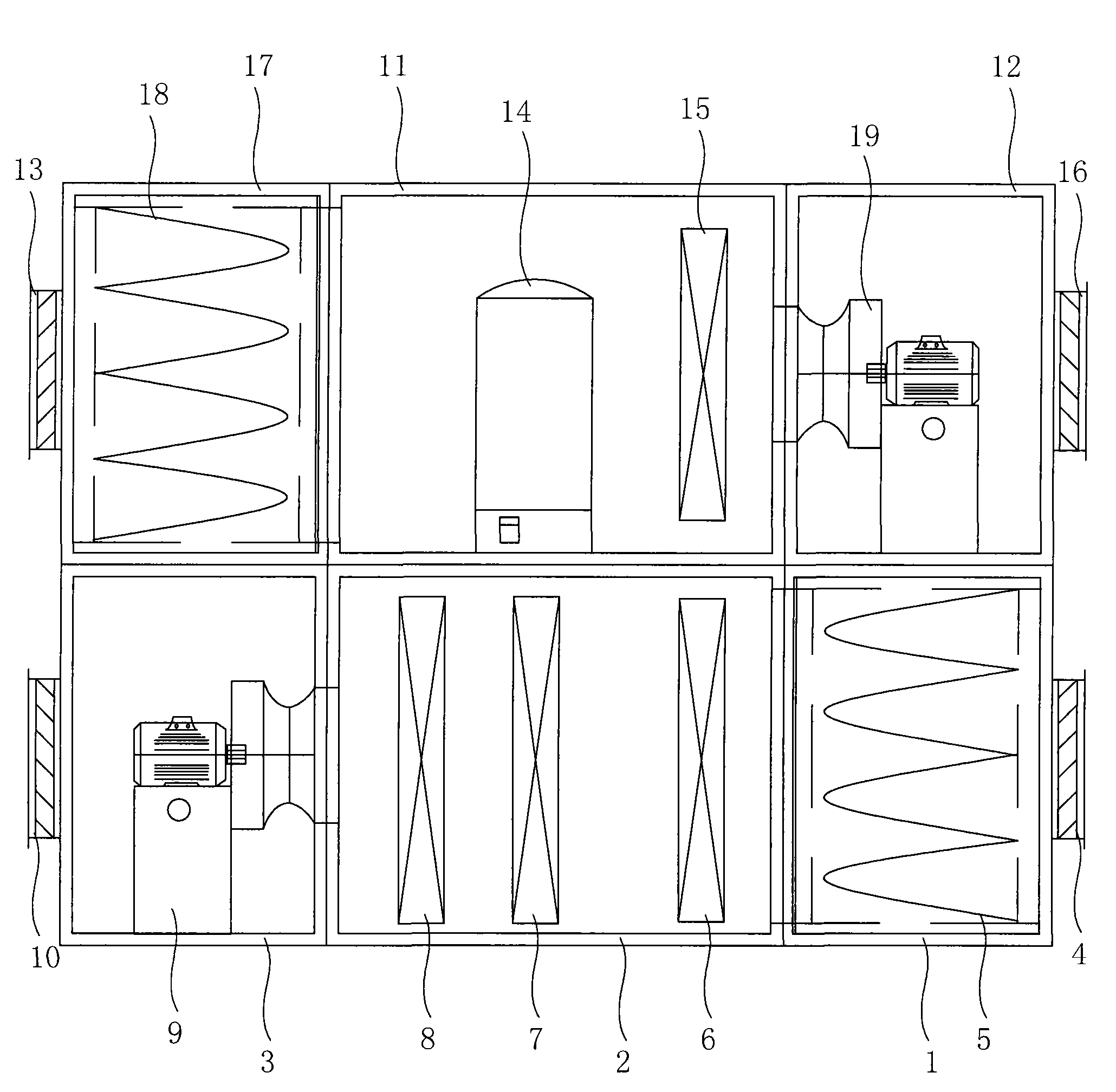
[0025] Embodiment one: see figure 1 As shown, a heat recovery fresh air unit includes an air intake unit, the air intake unit is provided with a filter section 1, a heat and humidity treatment section 2 and a fan section 3 in sequence, and a fresh air inlet 4 is provided in the filter section and an air filter 5, the heat and humidity treatment section 2 is provided with a water cooling coil 6, a direct evaporative coil 7 and a reheating coil 8, and the fan section 3 is provided with a fan 9 and an air outlet 10, so The water-cooling coil 6 is provided with a water inlet pipe and a water outlet pipe interface, and the direct evaporative coil 7 and the reheating coil 8 are provided with a refrigerant inlet and outlet interface, and also includes an outlet fan unit, the outlet fan unit A filter section 17, a heat recovery section 11 and an exhaust section 12 are provided in sequence, the filter section 17 is provided with a return air outlet 13 and an air filter 18, and the heat...


PUM


Abstract

The invention discloses a heat recovery fresh air unit, which comprises an air intake unit; the inside of the air intake unit is orderly provided with a filter section, a heat-moisture treatment section and a fan section; the inside of the filter section is provided with a fresh air intake and an air filter; the inside of the heat-moisture treatment section is provided with a water cooling coil, a direct evaporation type coil and a reheating coil; the inside of the fan section is provided with a fan and an air supply outlet; the water cooling coil is provided with water inlet pipe and water outlet pipe connectors; and the direct evaporation type coil and the reheating coil are provided with refrigerant inlet and outlet connectors. The heat recovery fresh air unit is characterized in that: the heat recovery fresh air unit also comprises an air outlet unit; the inside of the air outlet unit is orderly provided with a filter section, a heat recovery section and an air exhaust section; the inside of the filter section is provided with a return air inlet and an air filter; the inside of the heat recovery section is provided with a compressor and a condensing coil; and the air exhaust section is provided with a fan and an exhaust outlet. The heat recovery fresh air unit is provided with the air outlet unit, solves the problem of temperature and humidity control in the indoor environment, and can recover heat to further improve energy utilization rate.

Description

technical field [0001] The invention relates to an air treatment system, in particular to a fresh air treatment unit suitable for an air-conditioning water system. Background technique [0002] In daily life (in buildings), the air conditioning and ventilation system is used to achieve the corresponding temperature, humidity, cleanliness and sterility control requirements to provide the required hygienic, safe and comfortable air environment control. Most of the existing air-conditioning systems use primary return air or secondary return air. The air in each room is mixed and treated in the air-conditioning box through the return air duct, and then re-sent to each room, which can easily cause horizontal diffusion of pollution. , causing cross-infection, that is to say, as long as there are viruses and bacteria in a room, it is easy to spread quickly through the air-conditioning return air duct and air supply system in the entire building; The flooding caused by it is the bi...

Claims


Application Information

Patent Timeline
Patent Type & Authority Applications(China)
IPC IPC(8): F24F3/00F24F13/28F24F12/00F24F13/30
Inventor 俞卫刚沈晋明
Owner SUZHOU UNIV
Why Eureka
Try Eureka