Airborne laser-fluorescence sea oil pollution probing device

A detection device and fluorescence technology, which is applied in the fields of optical device exploration, fluorescence/phosphorescence, material excitation analysis, etc., can solve the problems that satellite airborne technology is difficult to detect, and achieve the effect of high recognition rate

Active Publication Date: 2009-12-30
DALIAN MARITIME UNIVERSITY
View PDF0 Cites 18 Cited by
  • Summary
  • Abstract
  • Description
  • Claims
  • Application Information

AI Technical Summary

Problems solved by technology

[0002] For the monitoring of marine oil spills, the methods and means usually used are optical remote sensing and rada...

Method used


Image

  • Airborne laser-fluorescence sea oil pollution probing device
  • Airborne laser-fluorescence sea oil pollution probing device

Examples


Embodiment 1

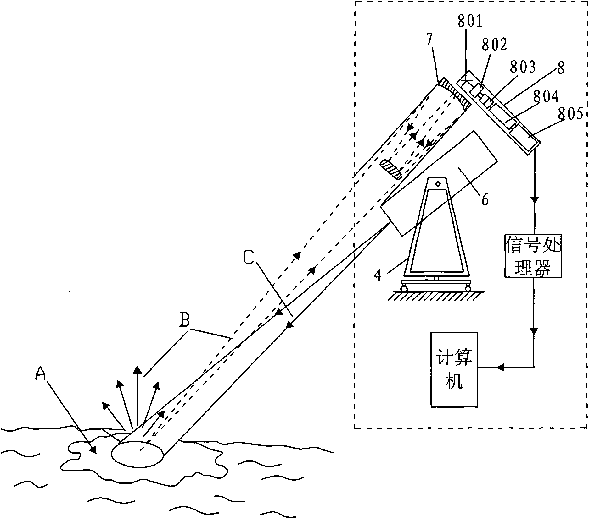
[0018] Embodiment 1: as figure 2 The shown laser fluorescence marine oil pollution detection device includes a laser 6 for emitting laser light to the surface of the detection object, a fluorescent telescope 7 for receiving the excited emission from the surface of the detection object, and for receiving the emitted fluorescence amplified by the telescope 7, After the spectrometer receives the fluorescence, especially the internal processor 804 performs spectral feature analysis to identify and analyze the type spectrometer 8 of the detected object; the telescope 7 uses a Cassegrain telescope; the laser 6 is a solid-state laser. the ultraviolet light; the spectrometer 8 adopts a fiber optic spectrometer, and its front receiving end includes: a mirror 801, a spectral filter 802 and a photomultiplier tube 803. The emitted fluorescence returned by the telescope 7 is identified and analyzed, and the spectrometer 8 is provided with a display unit 805 for displaying the category of ...

Embodiment 2

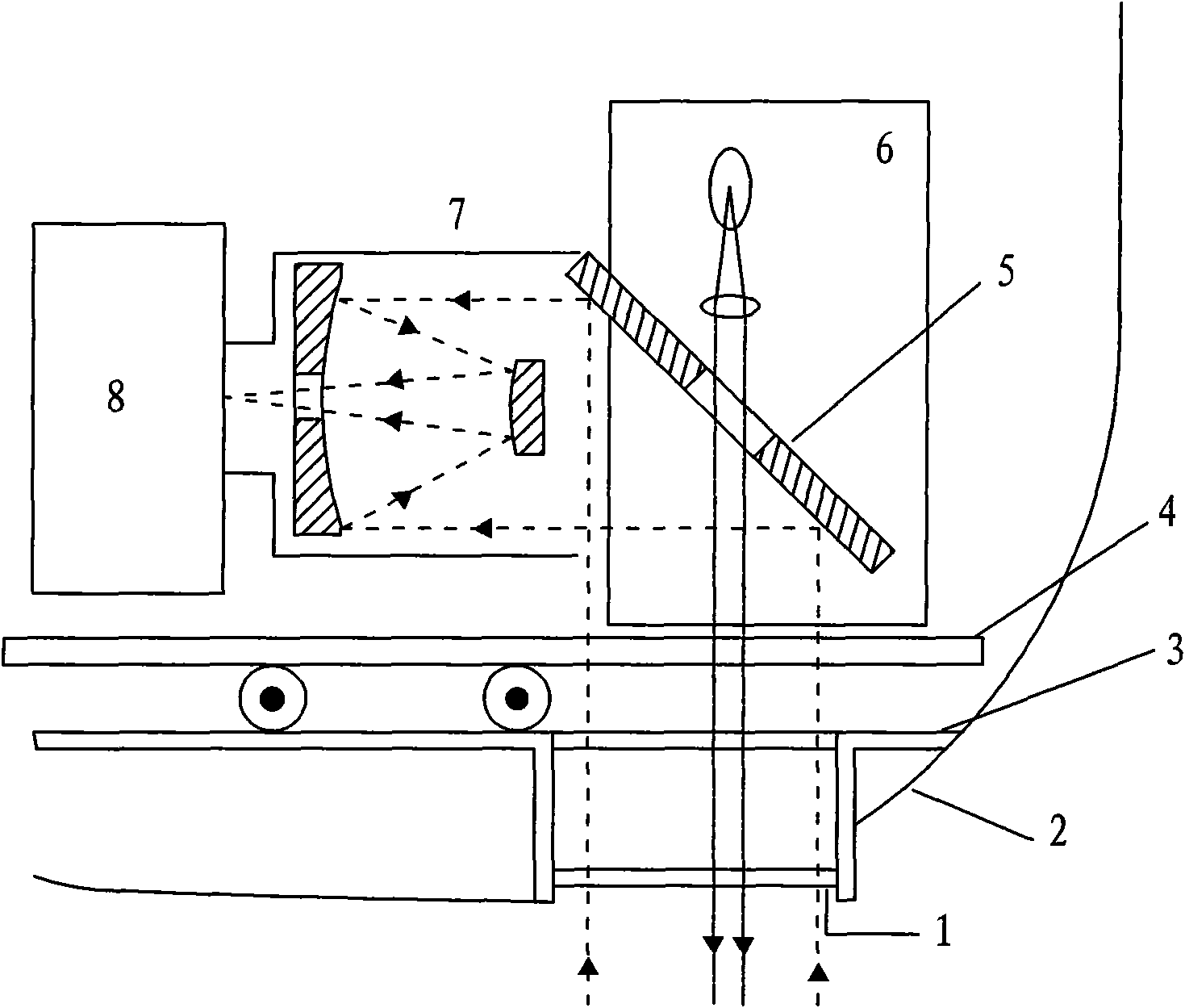
[0020] Embodiment 2: as figure 1 As shown, the principle and main devices of the laser fluorescent marine oil pollution detection device are the same as those of Embodiment 1, except that the laser 6, the telescope 7 and the spectrometer 8 are arranged as a whole; The half-mirror 5 is placed below with an inclination of 45°, and its lower reflecting surface corresponds to the telescope 7; the half-mirror 5 is provided with a light-transmitting hole to allow the laser light emitted by the laser 6 to pass through and scatter back The fluorescence is reflected to the viewing end of the telescope 7 according to its optical path; the spectrometer 8 is arranged at the rear of the observation end of the telescope 7 . In addition, the laser 6, the telescope 7 and the spectrometer 8 are fixed on the slide rail type support 4; the slide rail corresponding to the slide rail type support 4 is fixed on the carrier (in this embodiment, the slide rail is fixed on the aircraft by the aircraft...


PUM


Abstract

The invention discloses an airborne laser-fluorescence sea oil pollution probing device, which is characterized by comprising a laser, a telescope and a spectrometer. An area of a divergent light of each divergent angle generated by irradiating the surface of a probed object by the laser and a visual area of the telescope can maintain superposition, when the laser emits the laser light to irradiate on the surface of the probed object, the telescope receives fluorescence emitted by the probed object due to stimulation, and the amplified fluorescence is transmitted into the spectrometer by the light receiving terminal of the spectrometer through an observing terminal. The laser is used for emitting an ultraviolet light with a certain wavelength to irradiate on the surface of the probed object, and the fluorescence emitted by the surface of the probed object due to stimulation is amplified through the telescope and received by the spectrometer, and the spectrometer receives the fluorescence and analyzes the spectrum characteristic for analyzing the classification of the probed object; a moving window and a slide-rail support are arranged on an airplane so as to more conveniently and flexibly operate the whole device. The device can be widely applied to sea oil spilling probe in 24 hours, and utilizes the characteristic of the fluorescence with high identification ratio.

Description

technical field [0001] The invention relates to a marine oil spill detection device, in particular to an airborne laser fluorescence marine oil pollution detection device. Background technique [0002] For the monitoring of marine oil spills, optical remote sensing and radar technology are commonly used methods and means. However, satellites and other airborne technologies are difficult to detect new oil spills on the sea surface. [0003] Laser-excited fluorescence has good selectivity, high sensitivity, and strong recognition ability. In recent years, it has received more and more attention in environmental pollution monitoring and detection, and many laboratories have conducted in-depth research on it. The principle is that when a certain substance is excited by a beam of laser light, the molecules of the substance absorb energy and transition from the ground state to an excited state, and then emit fluorescence in the form of a radiative transition back to the ground sta...

Claims


Application Information

Patent Timeline
IPC IPC(8): G01V8/10G01V8/12G01N21/64
Inventor 李颖
Owner DALIAN MARITIME UNIVERSITY
Why Eureka
Try Eureka