Heat sink

A technology of a heat sink and a heat sink, which is applied in the directions of heat sinks, indirect heat exchangers, heat exchange equipment, etc., can solve the problems of small contact area, inability to achieve breakthrough improvement in heat dissipation performance, and inability to quickly transfer heat from heat pipes to heat sinks. , to achieve the effect of increasing the contact area and high heat dissipation performance

Inactive Publication Date: 2009-12-30
FU ZHUN PRECISION IND SHENZHEN +1
View PDF0 Cites 0 Cited by
  • Summary
  • Abstract
  • Description
  • Claims
  • Application Information

AI Technical Summary

Problems solved by technology

[0004] In order to make the radiator have a larger heat dissipation area as much as possible to accelerate heat dissipation, the heat sink usually has a larger size, and one end of the heat pipe is usually the evaporation end, and the other end is the condensation end, so that the condensation end is in contact with the heat sink. While the area of ​​the heat sink increases, the contact area between the heat pipe and it is smaller. Therefore, although the heat sink can quickly dissipate heat, the heat from the heat pipe cannot be quickly transferred to the heat sink, and the overall heat dissipation performance cannot be improved significantly.

Method used


Image

  • Heat sink
  • Heat sink
  • Heat sink

Examples


Embodiment Construction

[0012] The heat dissipation device of the present invention will be further described below with reference to the accompanying drawings.

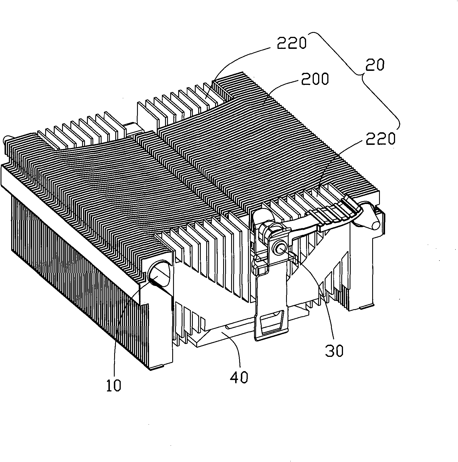
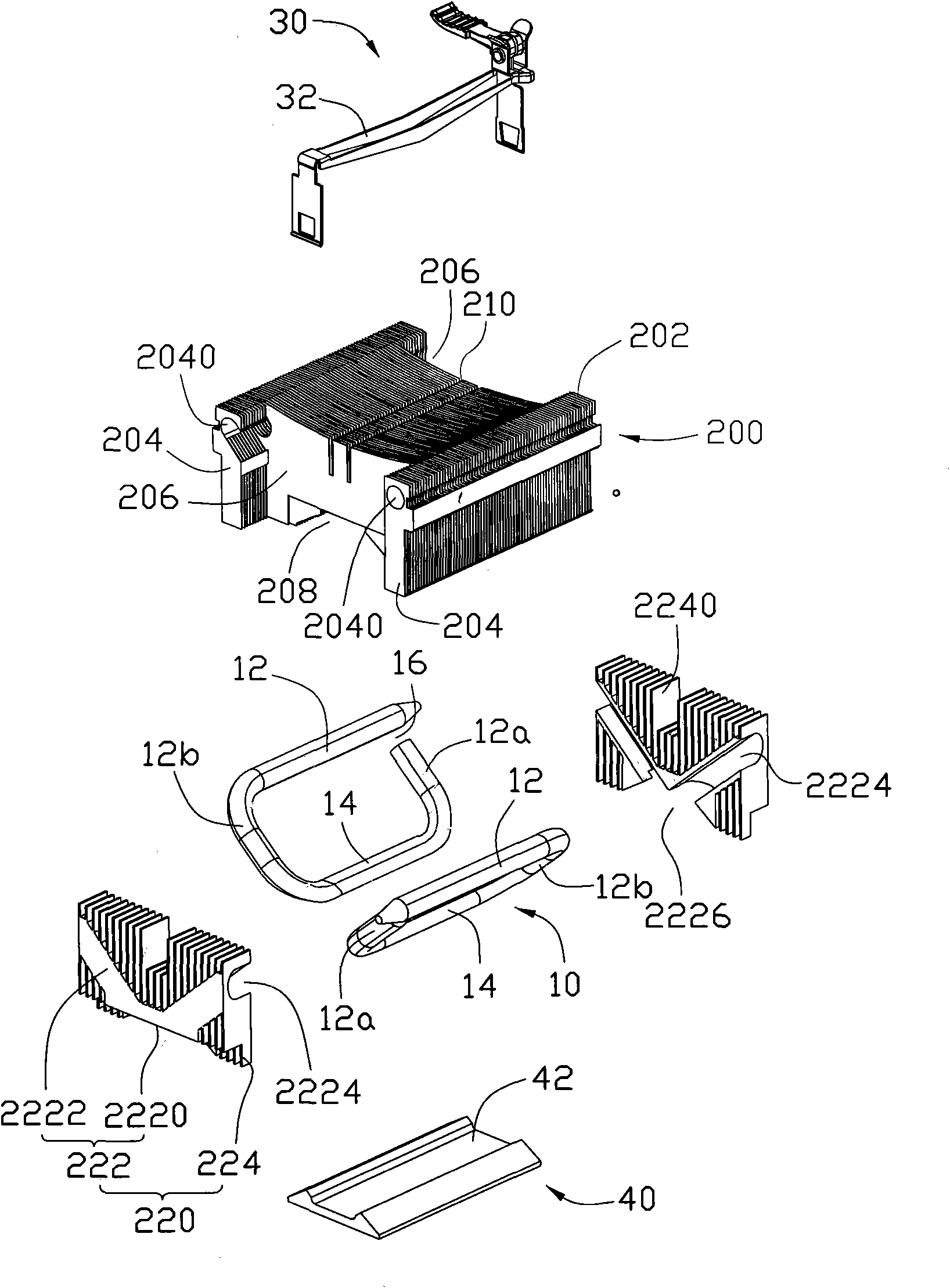
[0013] figure 1 and figure 2 Shown is a three-dimensional assembly and exploded view of a preferred embodiment of the heat dissipation device of the present invention. The heat dissipation device includes two heat pipes 10, a heat sink 20 and a fastener 30. The heat dissipation device cooperates with the fixing seat (not shown) on the circuit board (not shown) through the fastener 30 to make the heat dissipation The bottom end of the device 20 is in contact with a heat-generating electronic component (not shown) on the circuit board through a heat-absorbing plate 40, and absorbs its heat.

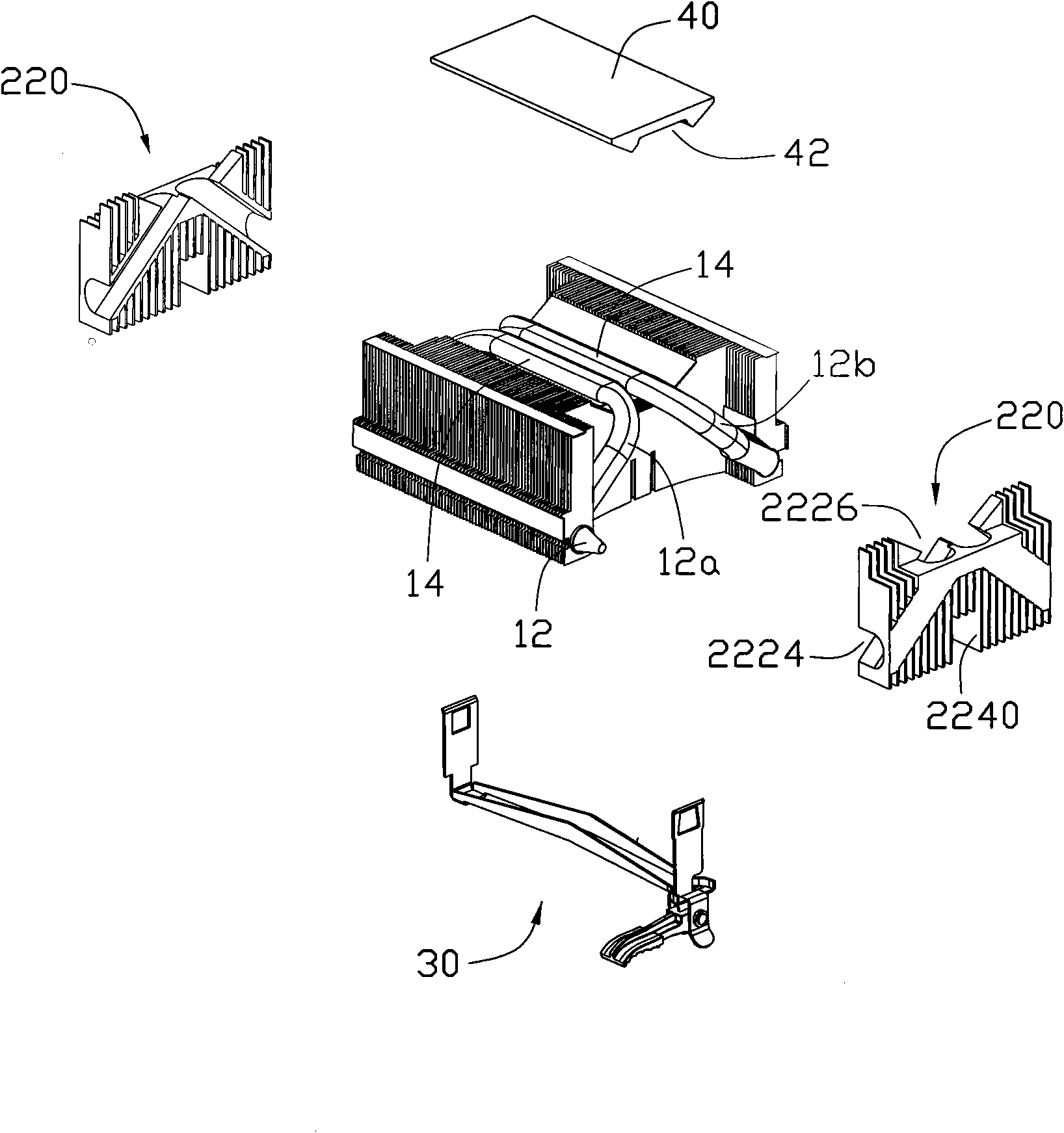
[0014] The two heat pipes 10 are disposed opposite to each other on the heat sink 20 . The heat pipes 10 are circular heat pipes bent and extended to form an open square frame structure. The sections where the two free ends of the heat pipe 10 of the...


PUM


Abstract

The invention discloses a heat sink, which comprises a radiator and a heat pipe, wherein the radiator comprises a body part and a plurality of radiating fins formed by extending in a radial form from the body part; the top face of the radiator is provided with a groove and a bearing face; the bearing surface surrounds the groove and is communicated with the groove; and the heat pipe is arranged on the groove and the bearing face in an extending mode. The heat sink forms the groove and the bearing face, and arranges the heat pipe in the groove and the bearing face, so that the heat can be more quickly and evenly distributed to the whole heat sink and emitted.

Description

technical field [0001] The invention relates to a heat dissipation device, in particular to a heat dissipation device for electronic components. Background technique [0002] With the continuous development of the electronic information industry, the operating frequency and speed of electronic components (especially the central processing unit) are constantly increasing. However, high frequency and high speed will increase the heat generated by electronic components, causing their temperature to rise continuously, which seriously threatens the performance of electronic components during operation. In order to ensure the normal operation of electronic components, a large amount of heat generated by electronic components must be discharged in time heat. [0003] Heat sinks of various structures are therefore continuously designed. With the continuous upgrading of heat generation, heat sinks that only dissipate heat through metal heat conduction can no longer meet the heat dis...

Claims


Application Information

Patent Timeline
Patent Type & Authority Applications(China)
IPC IPC(8): H05K7/20H01L23/34H01L23/427
CPCH01L21/4882H01L23/427F28D15/0275H01L23/467H01L23/4093F28D15/0266F28F1/32F28F2215/04H01L2924/0002H01L2924/00
Inventor 郭青磊朱寿礼方彝群
Owner FU ZHUN PRECISION IND SHENZHEN
Why Eureka
Try Eureka