Heat radiator with air pump separate type thermosiphon for machine room or machine cabinet

A heat dissipation device and thermosiphon technology, which is applied in household heating, application, heating methods, etc., can solve problems such as insufficient kinetic energy and unsatisfactory heat dissipation effect, and achieve prolonging service life, solving low utilization rate, and reducing energy consumption. Effect

Active Publication Date: 2010-01-06
BEIJING UNIV OF TECH
View PDF0 Cites 36 Cited by
  • Summary
  • Abstract
  • Description
  • Claims
  • Application Information

AI Technical Summary

Problems solved by technology

[0003] The present invention provides a thermal siphon cooling device with separate air pump for machine rooms or cabinets, aiming at reducing the cooling and heat dissipation energy consumption of machine rooms or cabinets, improving the reliability of internal equipment, prolonging the service life of equipment, and fundamen...

Method used


Image

  • Heat radiator with air pump separate type thermosiphon for machine room or machine cabinet
  • Heat radiator with air pump separate type thermosiphon for machine room or machine cabinet
  • Heat radiator with air pump separate type thermosiphon for machine room or machine cabinet

Examples


Embodiment 1

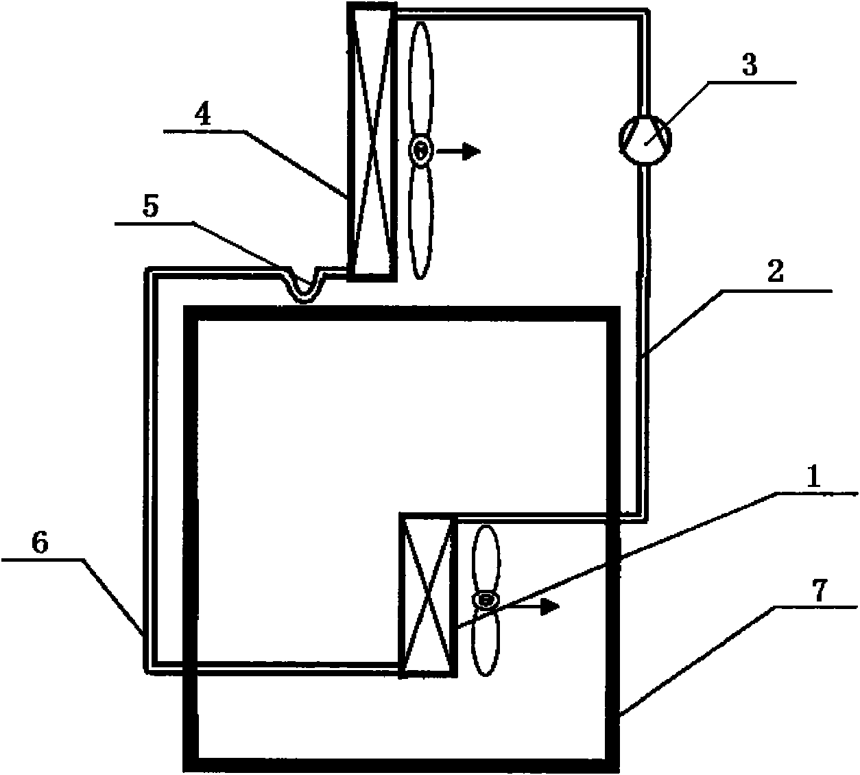
[0022] Embodiment 1: Heat exchanger with forced convection with air pump separate thermosiphon cooling device such as figure 1 As shown, the device includes an evaporator 1 with a fan installed in a machine room or cabinet 7, a forced convection condenser 4 installed outdoors, and an air pump 3 installed on a steam pipe 2; the upper part of the evaporator 1 passes through the steam pipe 2 The air pump 3 communicates with the upper part of the condenser 4; the bottom of the condenser 4 communicates with the bottom of the evaporator 1 through the liquid collecting pipe 6 and the U-shaped liquid storage bend 5; fans are installed on the evaporator 1 and the condenser 4 , using forced convection heat transfer. When the device is running, the fan of evaporator 1 starts, and the hot air in the machine room or cabinet 7 flows through the evaporator 1, heating the evaporator 1 to make the working fluid in it absorb heat and boil, at the same time, the hot air flowing through the evap...

Embodiment 2

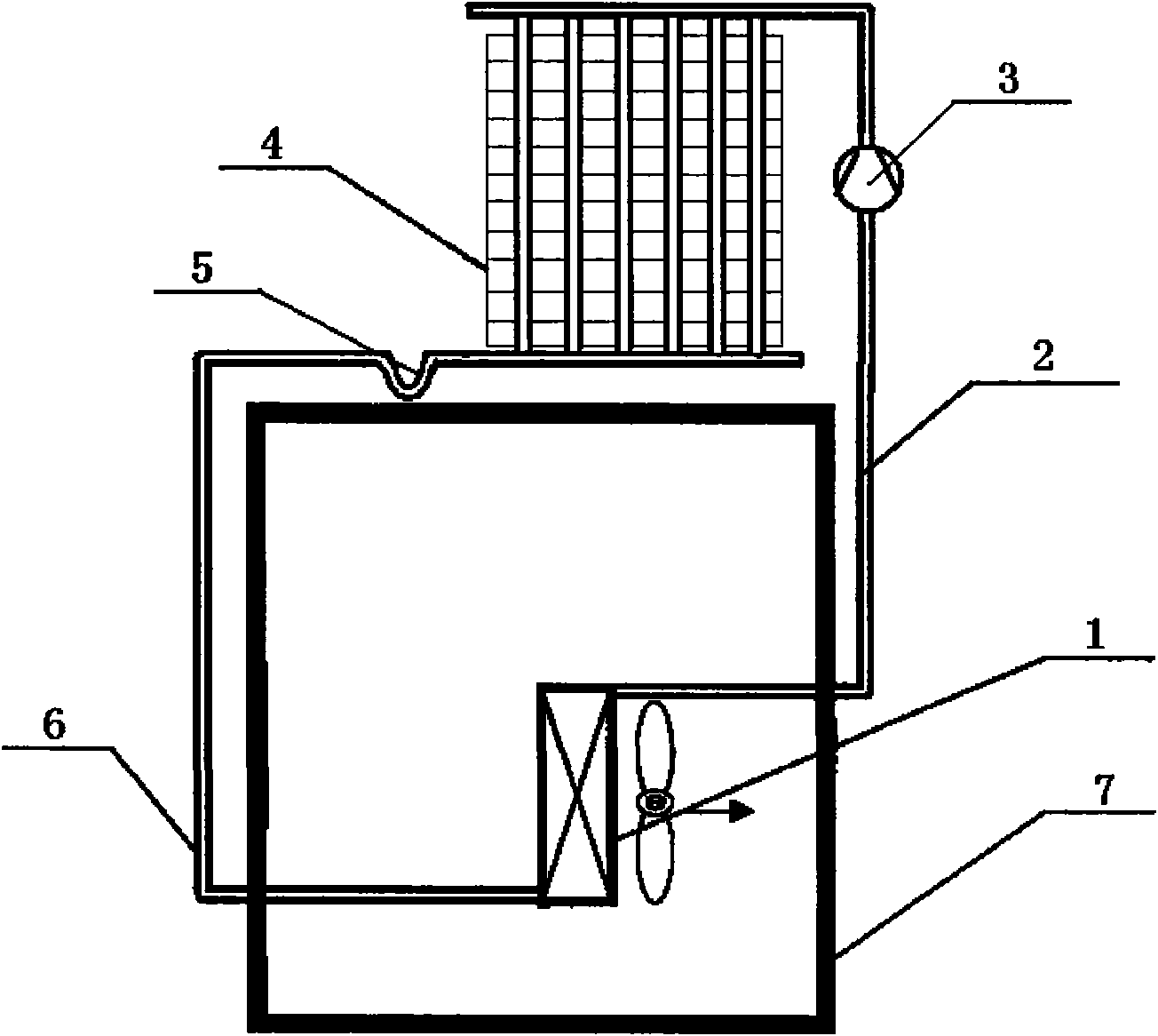
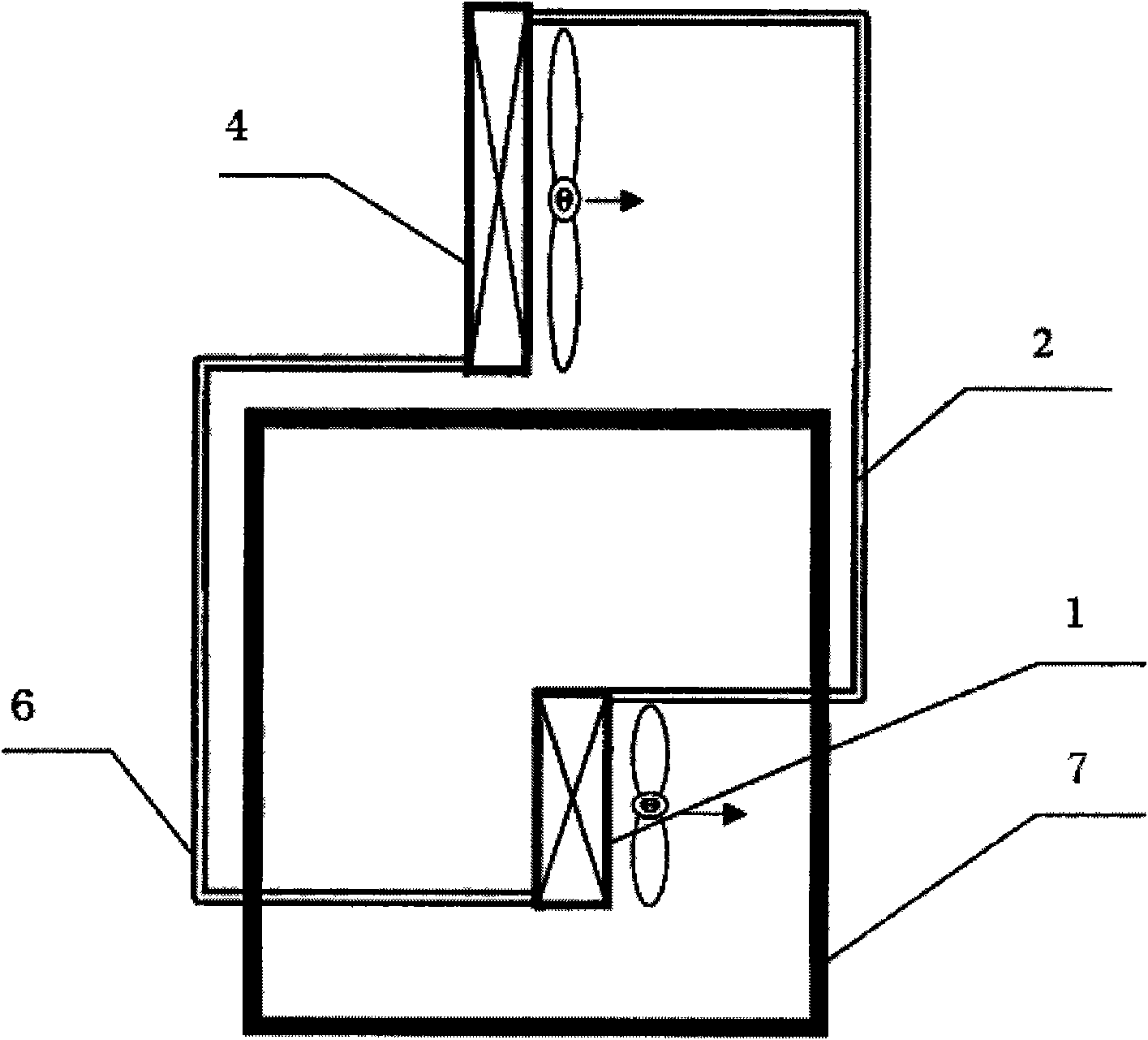
[0023] Embodiment 2: Heat exchanger natural convection with air pump separate type thermosiphon cooling device such as image 3As shown, the device includes an evaporator 1 with a fan installed in a machine room or cabinet 7, a natural convection condenser 4 installed outdoors, and an air pump 3 installed on a steam pipe 2; the upper part of the evaporator 1 passes through the steam pipe 2 The air pump 3 communicates with the upper part of the condenser 4; the bottom of the condenser 4 communicates with the bottom of the evaporator 1 through the liquid collecting pipe 6 and the U-shaped liquid storage bend 5; the evaporator 1 is equipped with a fan; the condenser 4 does not have The fan adopts natural convection heat exchange, such as a flat plate heat exchanger. When the device is in operation, the fan of evaporator 1 starts, and the hot air in the machine room or cabinet 7 flows through the evaporator 1 to heat the evaporator 1, and the working fluid in the evaporator 1 boils...


PUM


Abstract

The invention relates to a heat radiator with an air pump separate type thermosiphon for a machine room or machine cabinet, which belongs to the technical field of heat exchange of heat radiators. The heat radiator comprises an evaporator (1), a condenser (4), a liquid collecting pipe (6), a steam pipe (2), an air pump (3) and a liquid storage bend (5), wherein the condenser (4) is positioned on the upper part of the evaporator (1), the upper part of the evaporator (1) is communicated with the condenser (4) by the steam pipe (2) and the air pump (3), the bottom of the evaporator (1) is communicated with the bottom of the condenser through the liquid collecting pipe and a liquid storage bend, a seal space is formed in the hear radiator, and liquid working media are filled into the seal space. After the evaporator absorbs heat, the internal liquid working media in the seal space are gasified, steam is transmitted to the condenser by the air pump through the steam pipe, the liquid working media change into liquid after radiating heat to air around in the condenser and flow back to the evaporator through the liquid storage bend and the liquid collecting pipe, and thus, the heat radiator can radiate internal heat of a seal machine room to the atmosphere, increases the steam power of the working media and the utilization ratio of the condenser and has better heat radiating performance in a larger heat radiating range.

Description

technical field [0001] The invention relates to a heat dissipation device used in occasions requiring cooling such as a machine room or a cabinet, and belongs to the technical field of heat exchange of heat exchange equipment. Background technique [0002] In industrial computer rooms or cabinets, due to the long continuous operation of electrical equipment and large heat generation, special cooling equipment is required to dissipate the heat generated by the equipment or components to the atmosphere to maintain the ambient temperature in the computer room or cabinet and ensure the safety of the equipment. work normally. At present, the more common method is to use air-conditioning equipment to remove the heat from the working environment inside the computer room or cabinet, so as to achieve the purpose of cooling the computer room or cabinet. Although this heat dissipation and cooling method can meet the requirements of cooling and temperature control, the operation energy...

Claims


Application Information

Patent Timeline
IPC IPC(8): F24F5/00C09K5/04H05K7/20
Inventor 马国远周峰
Owner BEIJING UNIV OF TECH
Why Eureka
Try Eureka