Oxidizing solution separator provided with gas-liquid separating spray nozzle

A liquid separation and oxidizing liquid technology, applied in the direction of using liquid separation agent, separation method, dispersed particle separation, etc., can solve the problems of chaotic gas-liquid interface, large pipeline vibration, hidden safety hazards, etc., to achieve stable gas-liquid interface, eliminate liquid Vortex, prevent fire explosion effect

Inactive Publication Date: 2010-01-13
山东晋控明水化工集团有限公司
View PDF0 Cites 1 Cited by
  • Summary
  • Abstract
  • Description
  • Claims
  • Application Information

AI Technical Summary

Problems solved by technology

[0004] 1. The oxidizing liquid gas-liquid separator in the prior art adopts a straight pipe insertion method at the inlet, and the gas-liquid separation occurs naturally during the free-falling process after the mixed liquid of oxidizing liquid and air enters the separator, so as to achieve complete gas-liquid separation large separation space
[0005] 2. When the oxidizing liquid and air enter the separator, the flow rate drops rapidly, causing a large impact in the equipment, and the gas-liquid interface in the container is chaotic, which makes it difficult to control and stabilize the liquid level in the container. It is very difficult for the operator to adjust. The low-level gas is connected to the oxidation liquid tank through the outlet pipe of the separator, causing the material to run out and jeopardizing the safety of production
Since there is no anti-swirl device at the outlet of the separator, the liquid entrains a large amount of gas into the storage tank, causing disturbance in the storage tank, resulting in pressure in the normal pressure storage tank and large vibration of the pipeline, which causes a greater safety hazard to production
The above reasons have become factors restricting the increase of production load and threatening production safety.

Method used


Image

  • Oxidizing solution separator provided with gas-liquid separating spray nozzle
  • Oxidizing solution separator provided with gas-liquid separating spray nozzle
  • Oxidizing solution separator provided with gas-liquid separating spray nozzle

Examples


Embodiment Construction

[0018] The oxidation liquid separator with gas-liquid separation nozzle of the present invention will be described in detail below with reference to the accompanying drawings.

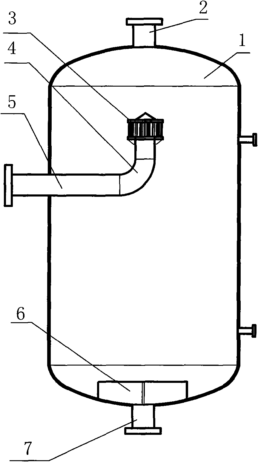
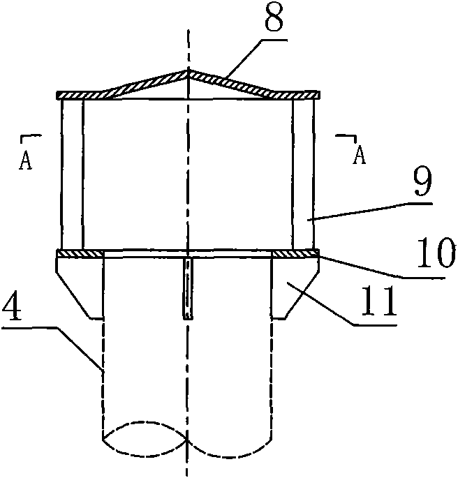
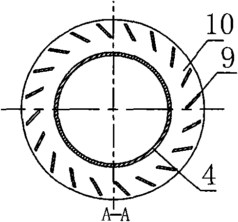
[0019] The structure of the oxidizing liquid separator with gas-liquid separation nozzle of the present invention is composed of a shell 1, a material inlet 5 and a material outlet 7, and the material inlet end in the shell 1 is connected by an upwardly bent elbow 4. The swirl nozzle 3 is provided with an anti-rotation stabilizer 6 above the material outlet 7 at the bottom of the shell 1, wherein the swirl nozzle 3 is composed of a cap 8, guide vanes 9 and an annular base 10, and the guide vanes 9 are vertical Welded between the cap 8 and the annular base 10, the bottom of the annular base 10 is provided with a rib plate 11, the annular base 10 is connected with the upper end of the elbow 4 through the rib plate 11, and the anti-rotation current stabilizer 6 is made of stainless steel plate Vertical we...


PUM


Abstract

The invention provides an oxidizing solution separator provided with a gas-liquid separating spray nozzle, which has the structure of consisting of a shell, a material inlet and a material outlet; wherein the end of the material inlet positioned inside the shell is connected with a rotary spray nozzle by an elbow pipe bending upwards; an anti-rotation flow stabilizer is arranged above the material outlet positioned at the bottom of the shell; wherein the rotary spray nozzle consists of a cap cover, a guide vane and a ring-shaped base, the guide vane is vertically welded between the cap cover and the ring-shaped base, a rib plate is arranged at the bottom of the ring-shaped base, the ring-shaped base is connected with the upper end of the elbow pipe by the rib plate, and the anti-rotation flow stabilizer is formed by vertically welding a stainless steel plate at the bottom of the shell. The oxidizing solution separator has the advantages of improving the effect of gas-liquid separation, ensuring the safety of production and preventing production accidents.

Description

technical field [0001] The invention relates to chemical equipment, in particular to an oxidizing liquid separator with a gas-liquid separating nozzle for hydrogen peroxide production. Background technique [0002] The hydrogen peroxide production process uses 2-ethylanthraquinone (EAQ) as the carrier, and heavy aromatic hydrocarbons and trioctyl phosphate (TOP) as the mixed solvent to prepare a solution with a certain composition (hereinafter referred to as the working solution). The hydrogen gas is passed together into a fixed-bed hydrogenator equipped with a catalyst, and the hydrogenation reaction is carried out at a certain pressure and temperature to obtain the corresponding 2-ethylhydroanthraquinone (HEAQ) solution (hereinafter referred to as the hydrogenation solution). The liquid pump enters the oxidation tower. The oxidation tower is an empty tower composed of two sections. The hydrogenated liquid entering the bottom of the upper section of the tower and about 450...

Claims


Application Information

Patent Timeline
Patent Type & Authority Applications(China)
IPC IPC(8): B01D47/06C01B15/023
Inventor 张金骏宋子兴于兴辉苗成祥延增银郭彦超殷传光郭雨霖
Owner 山东晋控明水化工集团有限公司
Why Eureka
Try Eureka