Polyurethane product and preparation method thereof and special equipment thereof
A special equipment, polyurethane technology, applied in the field of polyurethane products, can solve problems such as product deformation, achieve the effect of solving deformation and highlighting substantive characteristics
- Summary
- Abstract
- Description
- Claims
- Application Information
AI Technical Summary
Problems solved by technology
Method used
Image
Examples
Embodiment 1
[0050] Example 1, such as Figure 14 , the magnet 21 is installed on the upper mold 3, the magnet 21 is embedded in the upper mold 3 after wrapping the diamagnetic material 22, the final magnet 21, the diamagnetic material 22 and the surface of the upper mold 3 are flush, the magnet 21 is cylindrical, and the placed The positions are distributed along the shape of each upper metal insert 5, at least one at both ends, the upper metal insert 5 is in the shape of a strip, at least two, and separated by a certain distance on the mold, it can also be a ring, by means of The attraction between the magnet 21 that is flat with the upper mold body and the upper metal insert 5 fixes the upper layer of glass fiber felt 1 on the upper mold 3 surface.
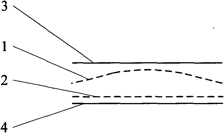
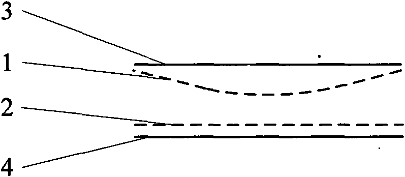
[0051] Such as Figure 4 , the bottom glass fiber mat 2 can be directly placed on the surface of the lower mold 4 without inserts fixed; the upper layer of glass fiber mat 1 is placed on the surface of the upper mold 3, and the upper mold ...
Embodiment 2
[0053] Embodiment 2, magnet 21 is set respectively on upper mold 3 and lower mold 4, and magnet 21 is embedded upper and lower mold after wrapping diamagnetic material 22, and final magnet 21, diamagnetic material 22 and mold surface are flush, and magnet 21 is cylindrical, and the placement position is distributed along the shape of each insert, at least one at each end, and the inserts are strip-shaped, at least two, and separated by a certain distance on the mold;
[0054] Place the bottom glass fiber mat 2 on the lower mold 4, and fix the bottom glass fiber mat 2 on the lower mold 4 through the lower metal insert 6, and put the upper glass fiber mat 1 on the upper mold 3, and also pass the upper metal insert 5 Fix the upper layer of glass fiber mat 1 on the upper mold 3, the lower metal insert 6 and the upper metal insert 5 are two strips, corresponding to the magnet 21 on the mold respectively, after pouring 1000g of polyurethane composite material, close the mold, After ...
Embodiment 3
[0056] Embodiment 3, a magnet 21 is set on the upper mold 3, and the magnet 21 is embedded in the upper mold 3 after wrapping the diamagnetic material 22. Finally, the magnet 21, the diamagnetic material 22 and the surface of the upper mold 3 are flush, and the upper metal insert 5 is a strip-shaped and ring-shaped combination, the strip-shaped inserts are separated by a certain distance on the upper mold, and the ring-shaped inserts are arranged around the pouring port 9 at the geometric center of the upper mold;
[0057] Place the bottom glass fiber mat 2 on the lower mold 4, the upper glass fiber mat 1 is fixed on the upper mold 3 through the strip-shaped upper metal insert 5, and the upper layer of glass fiber mat is fixed by the ring-shaped upper metal insert 5 near the pouring port 9 1. After the mold is closed, pour the combined material, open the mold after aging, and take out the product.
[0058] Because the annular metal insert near the sprue plays a good role in fi...
PUM
| Property | Measurement | Unit |
|---|---|---|
| thickness | aaaaa | aaaaa |
| length | aaaaa | aaaaa |
Abstract
Description
Claims
Application Information
 - R&D
- Intellectual Property
- Life Sciences
- Materials
- Tech Scout
- Unparalleled Data Quality
- Higher Quality Content
- 60% Fewer Hallucinations
Browse by: Latest US Patents, China's latest patents, Technical Efficacy Thesaurus, Application Domain, Technology Topic, Popular Technical Reports.
© 2025 PatSnap. All rights reserved.Legal|Privacy policy|Modern Slavery Act Transparency Statement|Sitemap|About US| Contact US: help@patsnap.com


