
Exhaust gas purification apparatus for internal combustion engine

An exhaust purification device and an internal combustion engine technology, which is applied to exhaust devices, internal combustion piston engines, exhaust gas treatment, etc., can solve the problems of inability to disperse the reducing agent and uneven distribution of the reducing agent, and achieve the effect of improving the reduction efficiency.

Inactive Publication Date: 2010-01-13
BOSCH CORP
View PDF1 Cites 22 Cited by
  • Summary
  • Abstract
  • Description
  • Claims
  • Application Information

AI Technical Summary

Problems solved by technology

[0008] However, in the exhaust purification device described in Patent Document 1, although the perforated plate is arranged in the middle of the flow direction of the exhaust gas, when the flow velocity of the exhaust gas is slow, the reducing agent may not be uniformly dispersed.
That is, although the reducing agent is atomized by the spray from the reducing agent injection valve and evaporated and diffused by the heat of the porous plate, when the flow rate of the exhaust gas is slow, the reducing agent cannot be uniformly dispersed throughout the exhaust gas. and it is possible to make the distribution of reducing agent uneven

Method used


Image

  • Exhaust gas purification apparatus for internal combustion engine
  • Exhaust gas purification apparatus for internal combustion engine
  • Exhaust gas purification apparatus for internal combustion engine

Examples


Embodiment Construction

[0040] Hereinafter, embodiments of an exhaust gas purification device for an internal combustion engine according to the present invention will be specifically described with reference to the drawings. However, the above-mentioned embodiment shows only one aspect of the present invention, does not limit the present invention, and can be changed arbitrarily within the scope of the present invention.

[0041]In addition, in the drawings, parts with the same reference numerals denote the same components, and description thereof will be appropriately omitted.

[0042] 1. Exhaust purification device

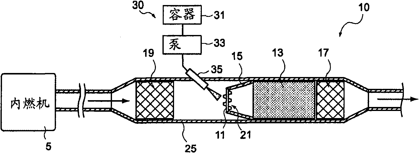
[0043] figure 1 A cross-sectional view showing an exhaust purification device for an internal combustion engine (hereinafter simply referred to as "exhaust purification device") 10 according to an embodiment of the present invention.

[0044] The exhaust purification device 10 of the present embodiment has: an internal combustion engine 5, which discharges exhaust gas; an exhaust p...


PUM


Abstract

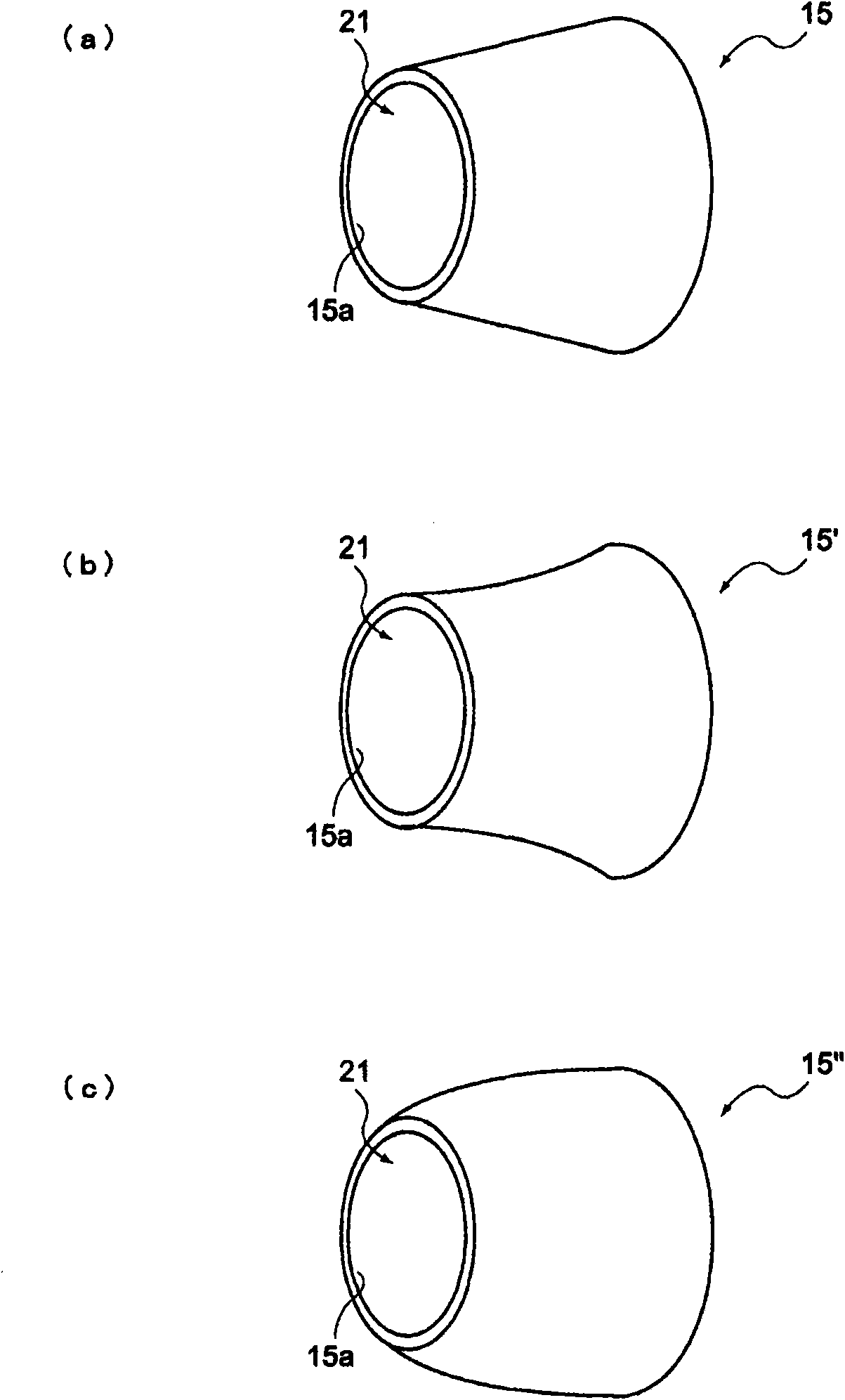
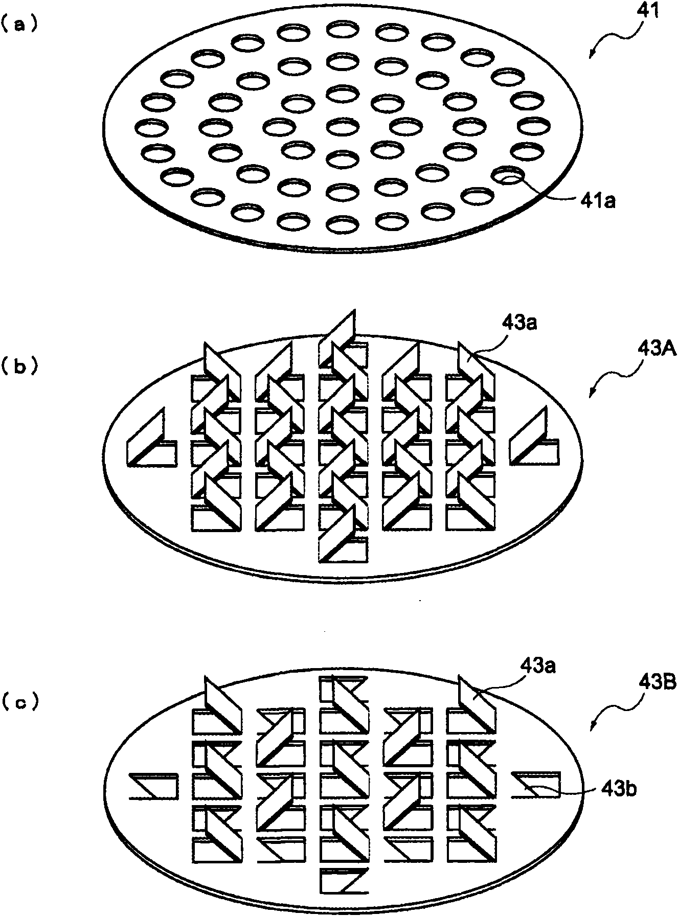
This invention provides an exhaust gas purification apparatus for an internal combustion engine, which can realize the flow of an exhaust gas with a reducing agent uniformly dispersed therein into an NOx catalyst disposed on the downstream side of the exhaust gas purification apparatus. The exhaust gas purification apparatus for an internal combustion engine comprises an NOx catalyst disposed in an exhaust path in the internal combustion engine and a reducing agent jetting part for injecting a reducing agent into the exhaust path on the upstream side of the NOx catalyst. The exhaust gas purification apparatus is characterized in that a throttle part is provided at a position on the downstream side of the reducing agent jetting part in its reducing agent jetting position and on the upstream side of the NOx catalyst so that the sectional area of the flow path in the throttle part is smaller than the sectional area of the exhaust path and the sectional area of the NOx catalyst and the throttle part comprises means for diffusing the reducing agent.

Description

technical field [0001] The invention relates to an exhaust purification device of an internal combustion engine, in particular to a NO X Catalyst for exhaust gas purification devices of internal combustion engines, the NO X The catalyst uses a reducing agent to reduce and remove NO in the exhaust gas X . Background technique [0002] Conventionally, it is known to remove particulate matter (hereinafter referred to as PM) and nitrogen oxides (hereinafter referred to as NO) contained in exhaust gas discharged from internal combustion engines such as diesel engines. X )Technology. [0003] Among them, as for the removal of NO X technology, the following selective reduction type exhaust purification device (SCR: Selective Catalytic Reduction) is known: X The upstream side of the catalyst injects the reducing agent into the exhaust passage, mixes the exhaust gas with the reducing agent, and then flows it into the NO X Catalyst, converts NO in the exhaust X (NO and NO 2 ) ...

Claims


Application Information

Patent Timeline
Patent Type & Authority Applications(China)
IPC IPC(8): F01N3/08F01N3/24F01N3/28B01D53/86B01D53/94
CPCB01D53/9431F01N2013/023F01N3/0814B01F5/0614B01D2251/20B01F5/0473F01N2013/026F01N3/2892B01D53/90B01F5/0618Y02T10/24F01N2470/30B01F5/0616F01N3/2066F01N2240/20B01F3/04049F01N2610/02F01N13/0097F01N13/0093Y02T10/12B01F23/2132B01F25/3141B01F25/4314B01F25/4316
Inventor 林美和宫本武司黑木史宏
Owner BOSCH CORP
Learn More