Shearing-type metal bending energy-wasting damper

A shear type, damper technology, applied in the direction of bridge parts, building components, bridges, etc., to achieve the effect of large deformation and simple and compact structure

Inactive Publication Date: 2010-01-20
TSINGHUA UNIV
View PDF1 Cites 21 Cited by
  • Summary
  • Abstract
  • Description
  • Claims
  • Application Information

AI Technical Summary

Problems solved by technology

[0003] The purpose of the present invention is to overcome the defects of metal energy dissipation dampers in the prior art, and provide a shear type metal bending energy dissipation damper with simple and compact structure, which can realize large shear force deformation

Method used


Image

  • Shearing-type metal bending energy-wasting damper
  • Shearing-type metal bending energy-wasting damper
  • Shearing-type metal bending energy-wasting damper

Examples


Embodiment 1

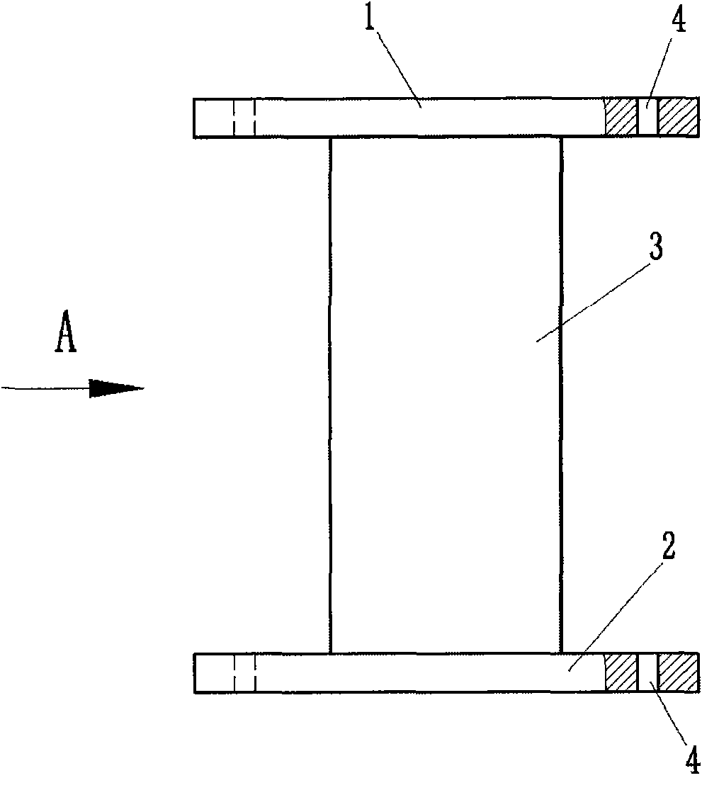
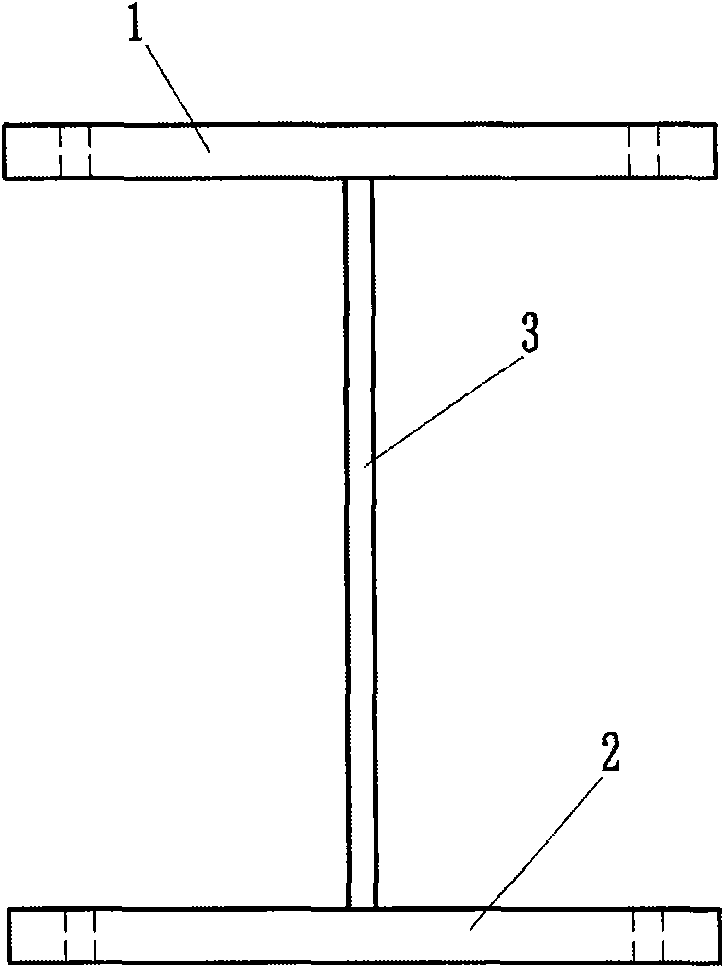
[0036] Such as figure 1 , figure 2 The shown shear type metal bending energy dissipation damper of the present invention includes an upper connection plate 1, a lower connection plate 2 and a core steel energy dissipation element, the core steel energy dissipation element is a steel plate 3 arranged on a plane, and the two ends of the steel plate 3 are respectively It is firmly welded together with the upper connecting plate 1 and the lower connecting plate 2. In order to facilitate the connection with other components, the upper connecting plate 1 and the lower connecting plate 2 are respectively provided with connecting structures for connecting with other structures. In this example, the connecting structures are through holes 4 .

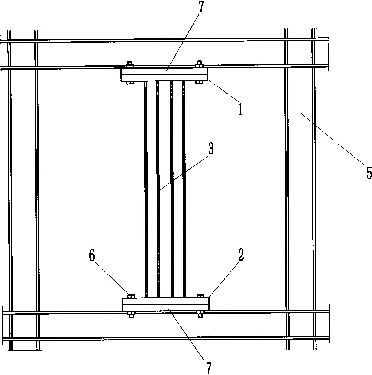
[0037] When used in frame structures, such as image 3 , Figure 4 As shown, the connecting flange 7 corresponding to the upper and lower connecting plates is welded and fixed on the steel frame 5, and the upper connecting plate 1 and the lo...

Embodiment 2

[0043] Based on the technical principle described in Embodiment 1, since the shear type metal bending energy dissipation damper of the present invention can achieve a large amount of deformation, the overall size of the present invention can be controlled to be small. Such as Figure 5 , Image 6 As shown, the difference from Embodiment 1 is that when the size of the shear type metal bending energy dissipation damper of the present invention is very small, an auxiliary bracket 9 can be added on the steel frame, and then the upper connecting plate 1 and the steel frame can be fixed. The provided connection flanges 7 are connected, and the lower connection plate 2 is connected with the connection flanges 7 fixedly provided on the auxiliary bracket 9 , so that the present invention is firmly connected to the steel frame 5 . When the steel frame 5 is deformed by the shear force F1 and F2, since the present invention uses a steel plate with a small bending stiffness as the energy-...

Embodiment 3

[0046] Such as Figure 7 , Figure 8 The difference between the shear type metal bending energy dissipation damper of the present invention and the first embodiment is that when the present invention is subjected to a shear load, the middle part of the core steel energy dissipation element bears a small moment, in order to reduce the system stiffness And to save steel, part of the material is appropriately cut off in the middle of the steel plate 3, and the steel plate 3 is made into an approximate "I" shape, so that the cross-sectional size of the middle part of the steel plate is smaller than the cross-sectional size of both ends. In addition, in order to withstand the large shear force and increase the number of steel plates, a total of three steel plates are set as the core steel energy-dissipating elements. When setting, the three steel plates are arranged parallel to each other, and an appropriate distance is reserved between each other as a reserved space for deformati...


PUM


Abstract

The invention relates to a shearing-type metal bending energy-wasting damper which belongs to the field of civil engineering structural damping technology, in particular to a metal damper used for damping and wasting energy. The shearing-type metal bending energy-wasting damper is characterized in that an adopted core metal energy-wasting element is at least one metal plate that realizes the energy-wasting capacity by bending, wherein two ends of the metal plate are respectively and fixedly connected with an upper connecting plate and a lower connecting plate and vertical to the upper connecting plate and the lower connecting plate; and the thickness direction of the metal plate is accordant with the direction of the shearing force borne by a building structure. The shearing-type metal bending energy-wasting damper realizes the energy wasting by utilizing favorable plastic deformation capacity of steel products, and the like as well as larger deformation quantity by utilizing the bending deformation, is easy to be processed and convenient and flexible for use, can effectively improve the anti-seismic performance of the building structure and a bridge structure, and has novel and reasonable structure, strong applicability and wide market popularization and application prospects.

Description

technical field [0001] The shear-type metal bending energy-dissipating damper belongs to the technical field of shock absorption of civil engineering structures, and specifically relates to a component or an energy-dissipating component of a building structure arranged between a bridge pier and a beam slab in bridge engineering, especially a kind of energy-dissipating component for shock-absorbing capable metal dampers. Background technique [0002] The development of today's buildings tends to be more and more tall, and the frame structure composed of steel members, composite members or reinforced concrete members is a structural form that is often used in buildings. In order to make the building structure have a strong ability to resist damage from external forces such as earthquakes or wind loads, it is often necessary to add metal energy-dissipating components to the frame structure. The development of bridge engineering tends to be more and more large-scale. In order t...

Claims


Application Information

Patent Timeline
Patent Type & Authority Applications(China)
IPC IPC(8): E04B1/98E01D19/00
Inventor 潘鹏徐培蓁叶列平
Owner TSINGHUA UNIV
Why Eureka
Try Eureka