Voltage controlled oscillator circuit
A voltage-controlled oscillator and circuit technology, applied in power oscillators, electrical components, automatic power control, etc., can solve the problem that the oscillation circuit cannot meet the requirements of low voltage, low noise and wide frequency adjustment range, and the anti-noise ability of the circuit system is reduced. Increase the phase noise of the oscillating circuit, and achieve the effect of simple structure, high reliability, and improved single-stage gain
- Summary
- Abstract
- Description
- Claims
- Application Information
AI Technical Summary
Problems solved by technology
Method used
Image
Examples
Embodiment 1
[0014] Embodiment 1: a kind of voltage controlled oscillator circuit (see figure 1 ), which is characterized in that it consists of four stages of identical fully differential unit circuits cascaded to each other.
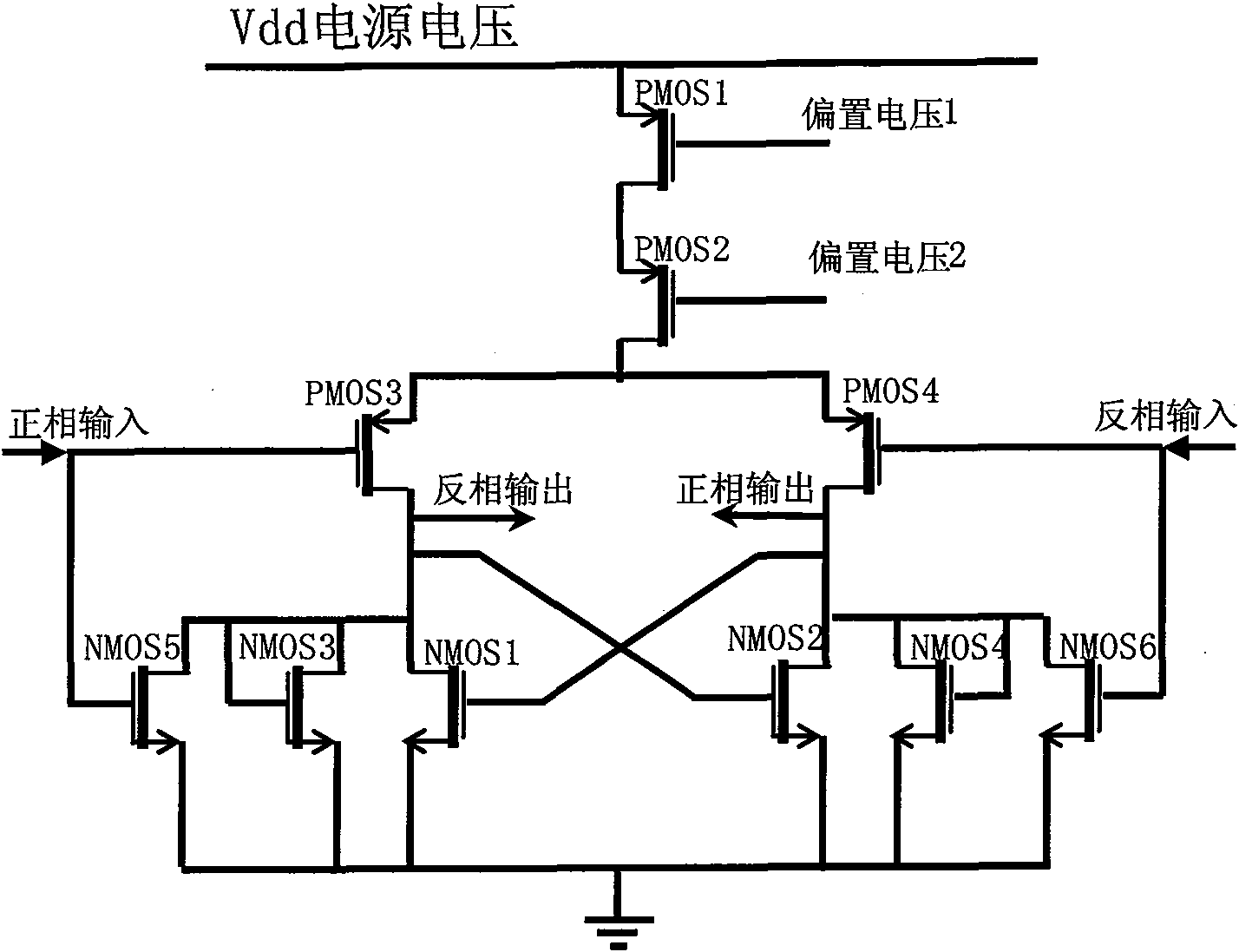
[0015] The full differential unit circuit mentioned above is a current source full differential unit circuit composed of transistor PMOS1 and transistor PMOS2 (see Figure 2-a ).
[0016] The above-mentioned current source fully differential unit circuit composed of transistor PMOS1 and transistor PMOS2 (see Figure 2-a ) includes a current source composed of transistor PMOS1 and transistor PMOS2, a differential input pair composed of transistor PMOS3 and transistor PMOS4, a positive feedback active load composed of transistor NMOS1 and transistor NMOS2, and a positive feedback active load composed of transistor NMOS3, transistor NMOS4, transistor NMOS5 and transistor A voltage clamping circuit composed of NMOS6 to limit the output signal amplitude; wherein, the ...
Embodiment 2
[0018] Embodiment 2: a kind of voltage controlled oscillator circuit (see figure 1 ), which is characterized in that it consists of four stages of identical fully differential unit circuits cascaded to each other.
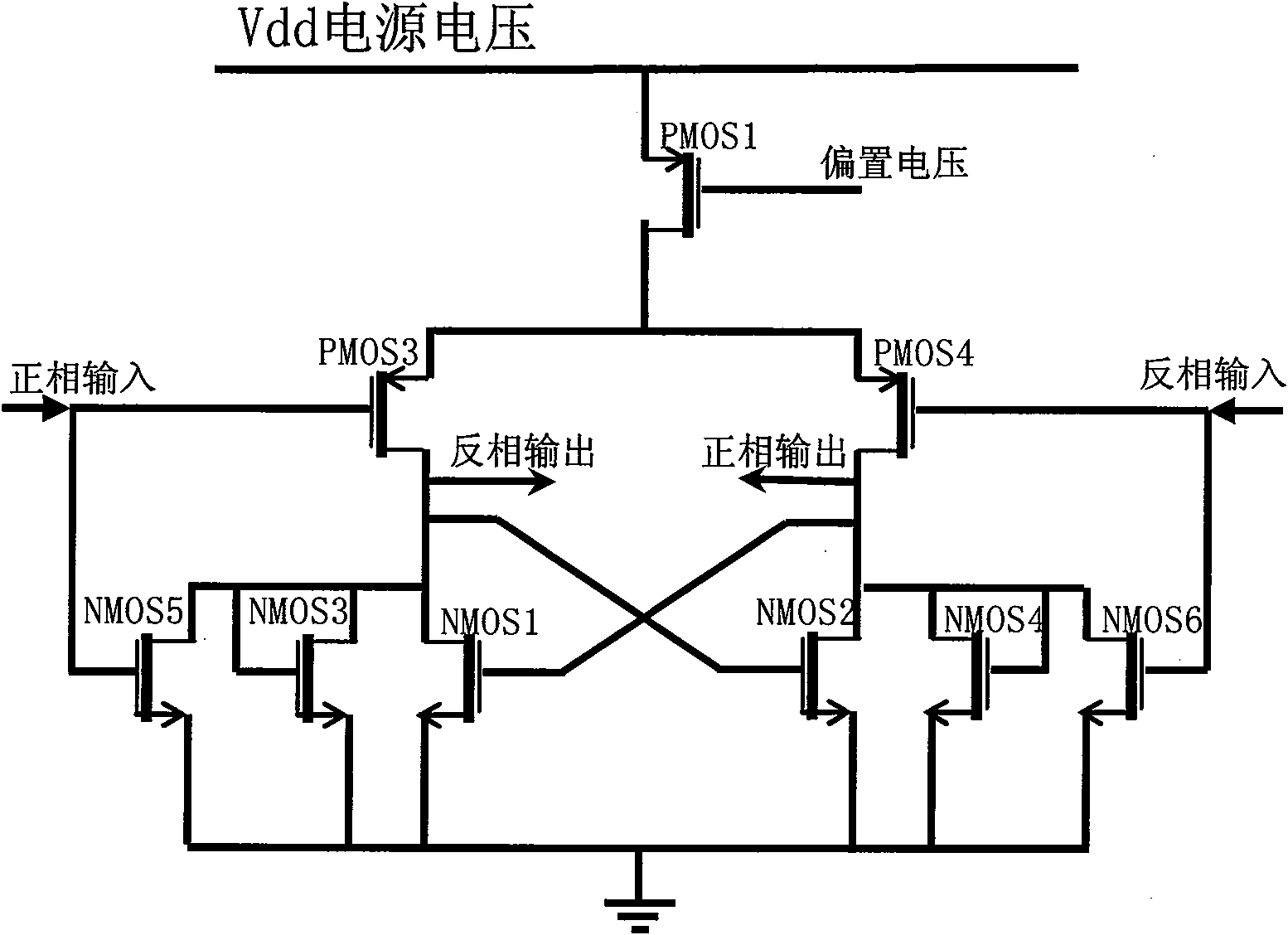
[0019] The full differential unit circuit mentioned above is a current source full differential unit circuit composed of transistor PMOS1 (see Figure 2-b ).
[0020] The above-mentioned current source full differential unit circuit composed of transistor PMOS1 (see Figure 2-b ) includes a current source composed of transistor PMOS1, a differential input pair composed of transistor PMOS3 and transistor PMOS4, a positive feedback active load composed of transistor NMOS1 and transistor NMOS2, and a current source composed of transistor NMOS3, transistor NMOS4, transistor NMOS5 and transistor NMOS6 A voltage clamping circuit for limiting the output signal amplitude; wherein, the source of the transistor PMOS1 is connected to the power supply, the gate is connected ...
PUM
 Abstract
Description
Claims
Application Information
 - R&D
- Intellectual Property
- Life Sciences
- Materials
- Tech Scout
- Unparalleled Data Quality
- Higher Quality Content
- 60% Fewer Hallucinations
Browse by: Latest US Patents, China's latest patents, Technical Efficacy Thesaurus, Application Domain, Technology Topic, Popular Technical Reports.
© 2025 PatSnap. All rights reserved.Legal|Privacy policy|Modern Slavery Act Transparency Statement|Sitemap|About US| Contact US: help@patsnap.com


