Fuselage structural component of an aircraft or spacecraft, with a foam layer as thermal insulation

A technology of structural components and foam layers, applied to aircraft parts, fuselage, fuselage bulkheads, etc., can solve the problems of reduced actual weight advantages and increased weight of CFK structures, and achieve the effects of simplifying cost savings and preventing condensation

Inactive Publication Date: 2010-01-20
AIRBUS OPERATIONS GMBH
View PDF0 Cites 12 Cited by
  • Summary
  • Abstract
  • Description
  • Claims
  • Application Information

AI Technical Summary

Problems solved by technology

Also this leads to an increase in weight which should only be saved by using CFK parts compared to metal parts
This results in a substantial reduction in the actual weight advantage of CFK structures in known fuselages

Method used


Image

  • Fuselage structural component of an aircraft or spacecraft, with a foam layer as thermal insulation
  • Fuselage structural component of an aircraft or spacecraft, with a foam layer as thermal insulation

Examples


Embodiment Construction

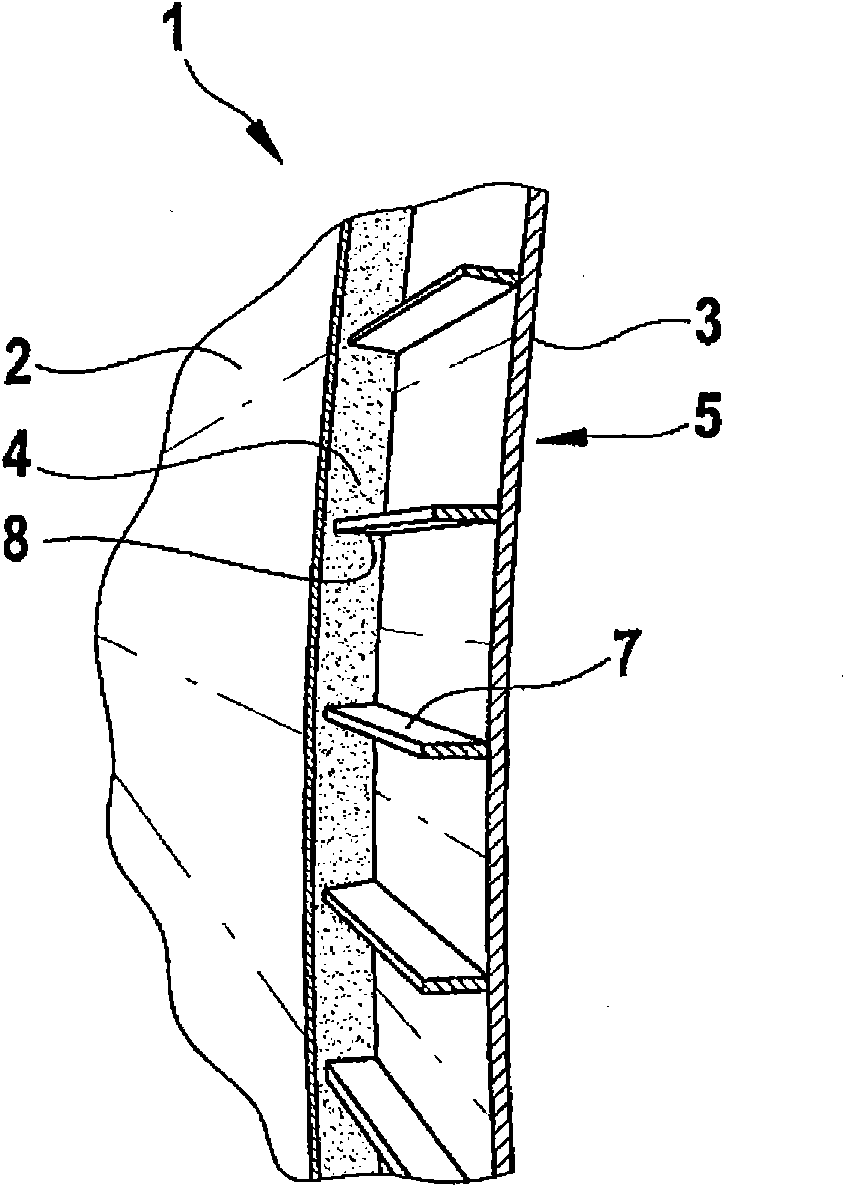
[0032] exist figure 1 A fuselage structural component 1 according to the invention is shown in detail in . The fuselage structural part 1 , which can be formed, for example, as a shell part or fuselage cylinder, has an outer shell or outer shell plate 2 and an inner frame structure 3 , in particular an inner shell or inner shell plate 3 . Said fuselage structural element 1 is then connected to the aircraft fuselage by means of rivets or other suitable fastening means, as known in the prior art. In this case, at least one foam layer 4 is arranged between the outer shell 2 and the inner shell 3 . The foam layer 4 is fastened on the outer shell 2 and / or the inner shell 3 by, for example, bonding.

[0033] Such as figure 1 As shown, the fuselage structural component 1 has an inner shell 3 forming a frame 5 . In this case the inner shell 3 can be formed as a one-piece lining, wherein the inner shell 3 can consist, for example, of a single piece of CFK prepreg. Optionally, the ...


PUM


Abstract

The present invention creates a fuselage structural component (1) of an aircraft or spacecraft, with a non- load-bearing outer skin (2) and a load-bearing inner framework structure (3), wherein a foam layer (4) which effects heat insulation and / or impact protection is arranged between the outer skin (2) and the inner framework structure (3).

Description

technical field [0001] The invention relates to a structural fuselage component for an aircraft or a dirigible, in which at least one foam layer is provided, said foam layer forming a thermal insulation layer. Background technique [0002] In cruising flight, the ambient temperature is typically around -50°C. Previous building materials used for fuselage construction absorbed this temperature over time with a corresponding surface temperature inside the fuselage. Therefore, a thermal insulation layer is provided on the inner side for the protection of passengers. However, this is exposed to air circulation. As a result, warm cabin air is continuously cooled on the cold inner surfaces of the fuselage structure. In this way, a large amount of condensed water cannot be avoided. The structure forces regular re-drying of the insulation, which traps 400 kg of moisture. Furthermore, protective measures against corrosion must be implemented and must be checked regularly. In th...

Claims


Application Information

Patent Timeline
Patent Type & Authority Applications(China)
IPC IPC(8): B64C1/00
CPCY02T50/46B64C1/40B64C1/12B64C1/068Y02T50/40
Inventor 米夏埃尔·柯拉克斯汉斯-彼得·温策尔沃尔夫迪特里希·多尔茨斯基拉尔夫·赫尔曼
Owner AIRBUS OPERATIONS GMBH
Why Eureka
Try Eureka