Supercharge Your Innovation With Domain-Expert AI Agents!

Combustion apparatus

一种燃烧设备、设备的技术,应用在热力学系统,热力学设备领域,能够解决活性不及它们等问题

Inactive Publication Date: 2014-03-12
EESTECH
View PDF3 Cites 0 Cited by
  • Summary
  • Abstract
  • Description
  • Claims
  • Application Information

AI Technical Summary

Problems solved by technology

Platinum and palladium are generally considered to be the most effective catalysts for low temperature complete oxidation, other catalysts have been tested but are not as active

Method used


Image

  • Combustion apparatus
  • Combustion apparatus
  • Combustion apparatus

Examples


Embodiment Construction

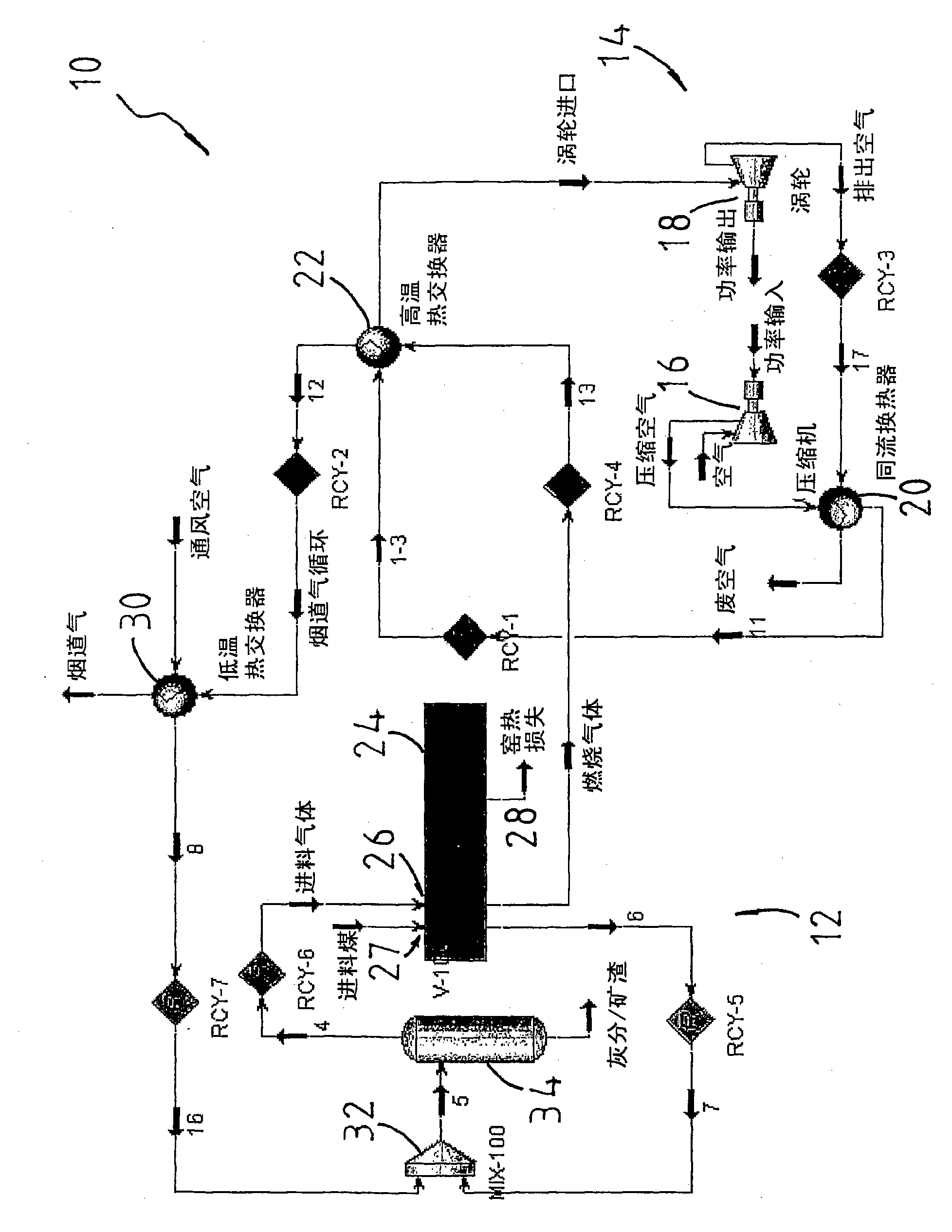
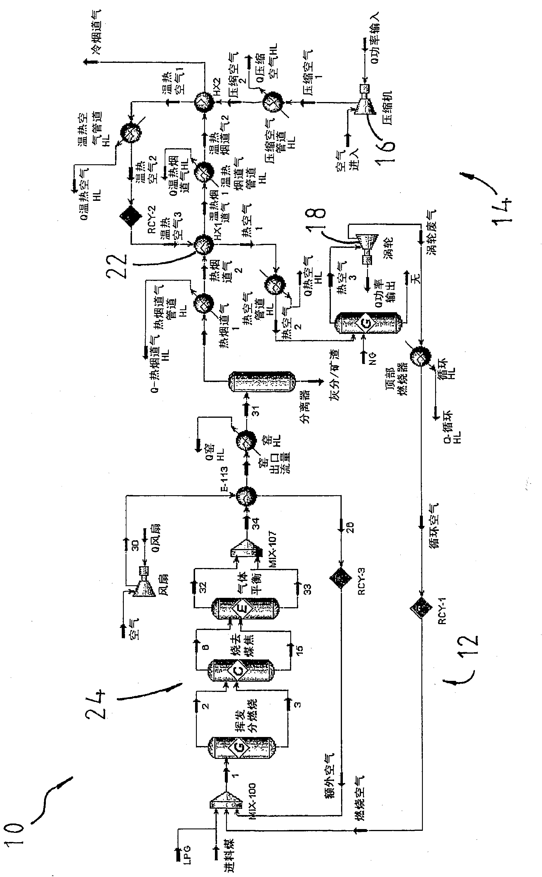
[0041] look first figure 2 , which shows a block diagram of a thermodynamic system 10 according to one embodiment of the invention. The system 10 has a combustion device 12 and a closed cycle thermodynamic device 14 . In this embodiment, the apparatus 14 is used to power a turbine engine.

[0042]The device 14 has a compressor 16 for compressing a working medium, in this case air. The compressed air from the compressor 16 is preheated with the exhaust air from the turbine 18 in the recuperator 20 . Then, the preheated compressed air is sent to the high temperature heat exchanger 22, from which the compressed air is returned to the turbine 18 to be expanded, and the turbine 18 is powered (power output) to perform work. In this case, a turbine drives a generator (not shown) to generate electricity.

[0043] The combustion plant 12 has a combustion unit in the form of a rotary kiln 24 with an inlet 26 with a port for feed gas and another port 27 for feed coal.

[0044] The ...


PUM

PropertyMeasurementUnit
calorific valueaaaaaaaaaa

Abstract

Provided is a combustion apparatus (10) for combusting one or more combustible media such as mine methane and waste coal. The apparatus has a combustion unit (24) with a fuel inlet (26,27) through which the combustible media enters the combustion unit for combustion therein, and a gas outlet (28) for gases formed during combustion to flow out of the combustion unit to provide heat energy to a downstream apparatus such as a turbine engine(14). The combustion unit is arranged to provide a volatile release reaction, a char combustion reaction and a gas phase reaction

Description

field of invention [0001] The present invention relates to a combustion apparatus for combusting a fuel medium, and in particular, but not limited to, a thermodynamic system having a combustion apparatus for combusting one or more lower fuel media and adapted to receive energy from the combustion apparatus Thermodynamic devices for heat energy. Background of the invention [0002] Known thermodynamic plants generally have a turbine with a built-in combustion chamber. The combustor is used to burn higher-grade fuels, such as high yielding coal. As a result, a considerable number of lower-grade resources such as low-rank coal, biomass, municipal waste, etc. are not utilized and considered as waste. These wastes are often piled open and are often seen as environmental sores. [0003] Methane (CH) in coal mine ventilation air 4 ) accounts for about coal mine CH 4 64% of emissions, but is difficult to use as an energy source because of the high volume of air in which methane...

Claims


Application Information

Patent Timeline
Patent Type & Authority Patents(China)
IPC IPC(8): C10J3/00F02C6/00
CPCF02C3/22Y02T50/671F23G5/46F02C6/18F02C3/28F23G5/20F23G7/06Y02T50/60
Inventor P·J·格林
Owner EESTECH
Features
  • R&D
  • Intellectual Property
  • Life Sciences
  • Materials
  • Tech Scout
  • Unparalleled Data Quality
  • Higher Quality Content
  • 60% Fewer Hallucinations
Learn More