Design method of line unwinding constant tension control device in line winding system

A technology of a control device and a design method, which is applied in the directions of transportation and packaging, transportation of filamentous materials, and processing of thin materials, etc., can solve the problems of poor quality, limited amplitude of up and down swing, and broken wire diameter of braided wire B.

Inactive Publication Date: 2010-01-27
苏州工业园区慧博自动化技术有限公司
View PDF0 Cites 24 Cited by
  • Summary
  • Abstract
  • Description
  • Claims
  • Application Information

AI Technical Summary

Problems solved by technology

[0004] 1) Since the tension rod 16 has a limited range of up and down swing, which is limited to about 90 degrees, when the instantaneous tension applied to the braided thread and silk B by the take-up main machine is too large, the tension rod 16 is very easy to swing down due to the instantaneous tension. To the limit, the braided wire B breaks or the wire diameter changes;
[0005] 2) As mentioned in the above item, because the braided wire and wire B often break or the wire diameter changes, the operator not only has trouble and inconvenience in wiring, but also causes uneven density and impedance of the finished braided products Even the disadvantage of poor quality of uneven tension;
[0006] 3) Due to the contact pr

Method used


Image

  • Design method of line unwinding constant tension control device in line winding system
  • Design method of line unwinding constant tension control device in line winding system
  • Design method of line unwinding constant tension control device in line winding system

Examples


Embodiment Construction

[0022] Aiming at the defects of the existing tension control device of the power pay-off machine, the present invention designs a design method of the tension control device of the power pay-off machine with a new structure to make it more practical.

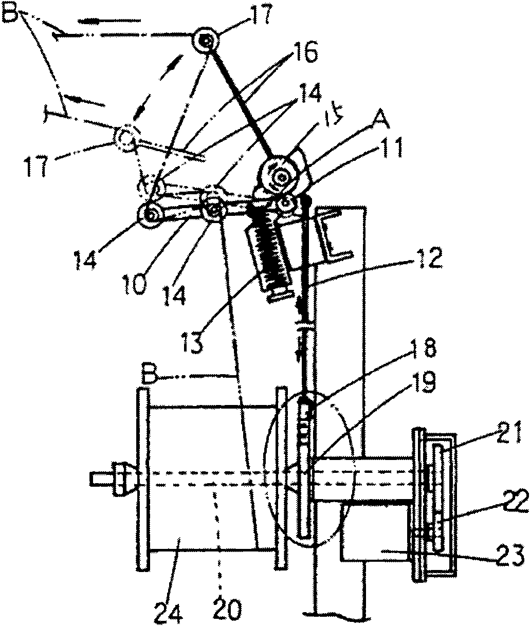
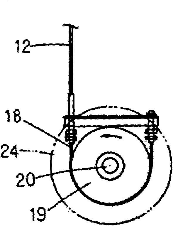
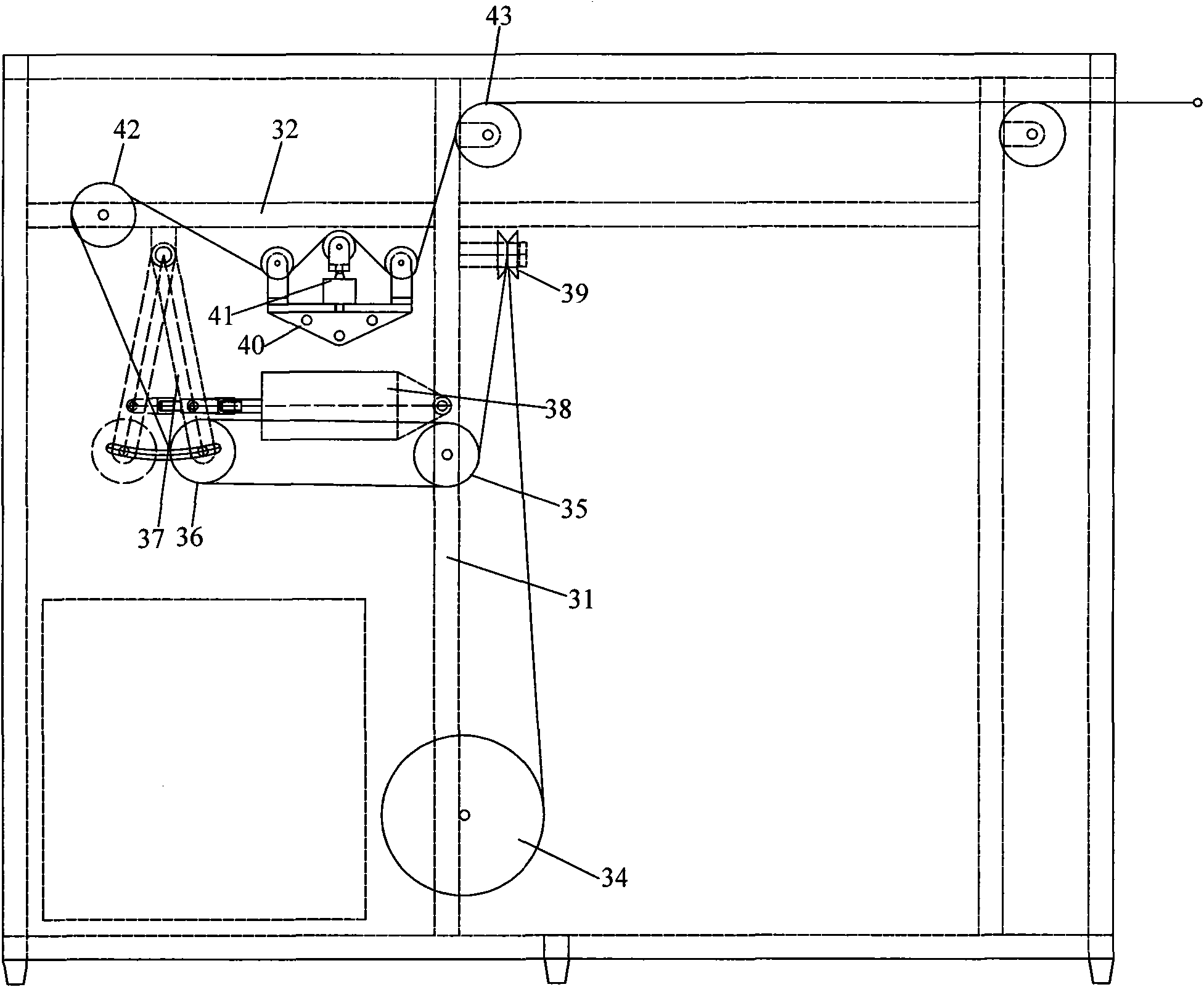
[0023] Such as figure 2 , image 3 As shown, the pay-off constant tension control device in the wire winding system can control the tension of one or more wire ropes. A servo motor 33 and a pay-off wheel 34 are installed at the bottom of the frame, and the servo motor 33 is driven by a drive element. Pay-off pulley 34, line is wound on the pay-off pulley 34; On the frame behind pay-off pulley 34, be provided with the pulley block of two fixed pulleys and a movable pulley, promptly the first fixed pulley 35 is installed on the side support 31, the second Two fixed pulleys 42 are installed on the upper bracket 32, the movable pulley 36 is between the first fixed pulley 35 and the second fixed pulley 42, the movable pulley 36 is ...


PUM


Abstract

The invention relates to a design method of a line unwinding constant tension control device in a line winding system. A servomotor and a line unwinding wheel are arranged on a frame, the line unwinding wheel is driven by the servomotor, a pulley block which comprises two fixed pulleys and a movable pulley is arranged on the frame behind the line unwinding wheel, the movable pulley is arranged between the two fixed pulleys and is arranged on a swing rod, the swing rod is articulated with the frame, an air cylinder is articulated on the frame, a piston rod of the air cylinder is connected with the swing rod in a driving mode, a tension sensor is arranged on the frame behind the pulley block, lines output by the line unwinding wheel are introduced into the tension sensor by the pulley block, and the lines which pass through the tension sensor are towed to a line winding host machine. The loading force of the air cylinder has a proportional relation with force and a force arm which act on the movable pulley of the swing rod, and the constant tension is ensured in a small angle. When the swing rod is lower than a balance position, inverse voltage is output to control the servomotor to wind the lines; when the swing rod is higher than the balance position, positive voltage is output to control the servomotor to unwinding the lines; and when used, the line unwinding content tension control device has higher stability.

Description

technical field [0001] The invention relates to a wire payout control device, in particular to a design method of a wire payout constant tension control device in a wire winding system. Background technique [0002] In the prior art, the embodiment in which metal wires (wires) or non-metal wires (wires) are made into industrial or civilian woven products is to pass various wires and wires wound on the take-up wheel through a pay-off wire in advance. The machine pulls and conveys to the take-up main machine one by one, so that each thread and thread can carry out the weaving action smoothly and without entanglement. Wherein, the pay-off machine is also provided with a tension control device. [0003] The setting and operation of the existing tension control device used in the pay-off machine, such as Figure 1a , Figure 1b As shown, it is mainly provided with a swing lever 10, which is pivoted by a pivot A so that both ends can swing up and down. One end is equipped with a...

Claims


Application Information

Patent Timeline
IPC IPC(8): B65H59/38B65H59/40
Inventor 陈永耀
Owner 苏州工业园区慧博自动化技术有限公司
Why Eureka
Try Eureka