Ground-road combined comprehensive tunnel for underground pipeline and trolley bus

A technology for trolleybuses and underground pipelines, applied in the fields of municipal and traffic engineering, can solve the problems of inability to lay pipelines in underground passages and the reduction of the scale of ventilation facilities, and achieve the effects of saving ventilation operation costs, improving carrying capacity, and improving passing capacity.

Inactive Publication Date: 2010-01-27
马兴华
View PDF2 Cites 11 Cited by
  • Summary
  • Abstract
  • Description
  • Claims
  • Application Information

AI Technical Summary

Problems solved by technology

[0012] The technical effect is: 1) organically combine ground roads, trolleybus underground passages and pipeline passages, and make full use of shallow space; 2) solve the problem of the setting of fixed overhead catenary and its contact with trolleybus rod-shaped current collectors , Fix the problem of lane setting, have the effect of bus-only lanes, and greatly improve the traffic speed, passing capacity and punctuality rate. A new form of public transportation makes trolleybuses still have strong vitality and can still play an important role in the urban traffic system; 3) Since trolleybuses are driven by electricity, the power facilities do not consume oxygen, do not emit waste gas, and the underground comprehensive passageway The ventilation facilities on the lower floor only need to meet the breathing needs of the drivers and passengers, and the scale of the ventilation facilities is greatly reduced, thereby greatly saving the cost of ventilation operation; 4) Solve the traffic contradiction between the trolley bus and other motor vehicles on the ground; 5) Free up the ground 6) It solves the problem that the current underground passage combined with the ground road cannot lay pipelines; 7) It has the function of a common ditch, which is convenient for pipeline laying and maintenance

Method used


Image

  • Ground-road combined comprehensive tunnel for underground pipeline and trolley bus
  • Ground-road combined comprehensive tunnel for underground pipeline and trolley bus
  • Ground-road combined comprehensive tunnel for underground pipeline and trolley bus

Examples


Embodiment 1

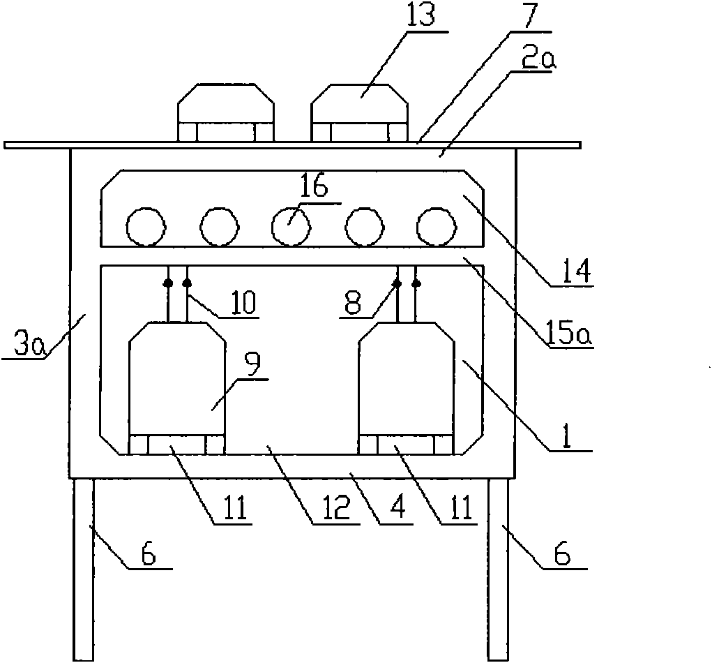
[0050] see figure 1 , using the shallow underground space of the ground road 7, combined with the ground road 7 to set up an underground comprehensive passage. Porous (not shown on the figure), the underground comprehensive passage lower layer 1 is used as the passage of trolley bus 9, the underground comprehensive passage upper layer 14 is used as the passage of pipeline 16, and the roof 2a top of the box culvert structure is laid with a surface layer as the ground road 7, and the underground comprehensive The side wall 3a or the top plate 2a of the channel upper layer 14 is provided with a special installation and inspection port (not shown in the figure), and the bottom of the middle plate and support 15a is provided with an overhead catenary 8, which is connected to the trolleybus current collector 10 to the trolleybus. 9 power supply, the ventilation facility (not shown on the figure) that only needs to satisfy the breathing needs of drivers and passengers on the lower fl...

Embodiment 2

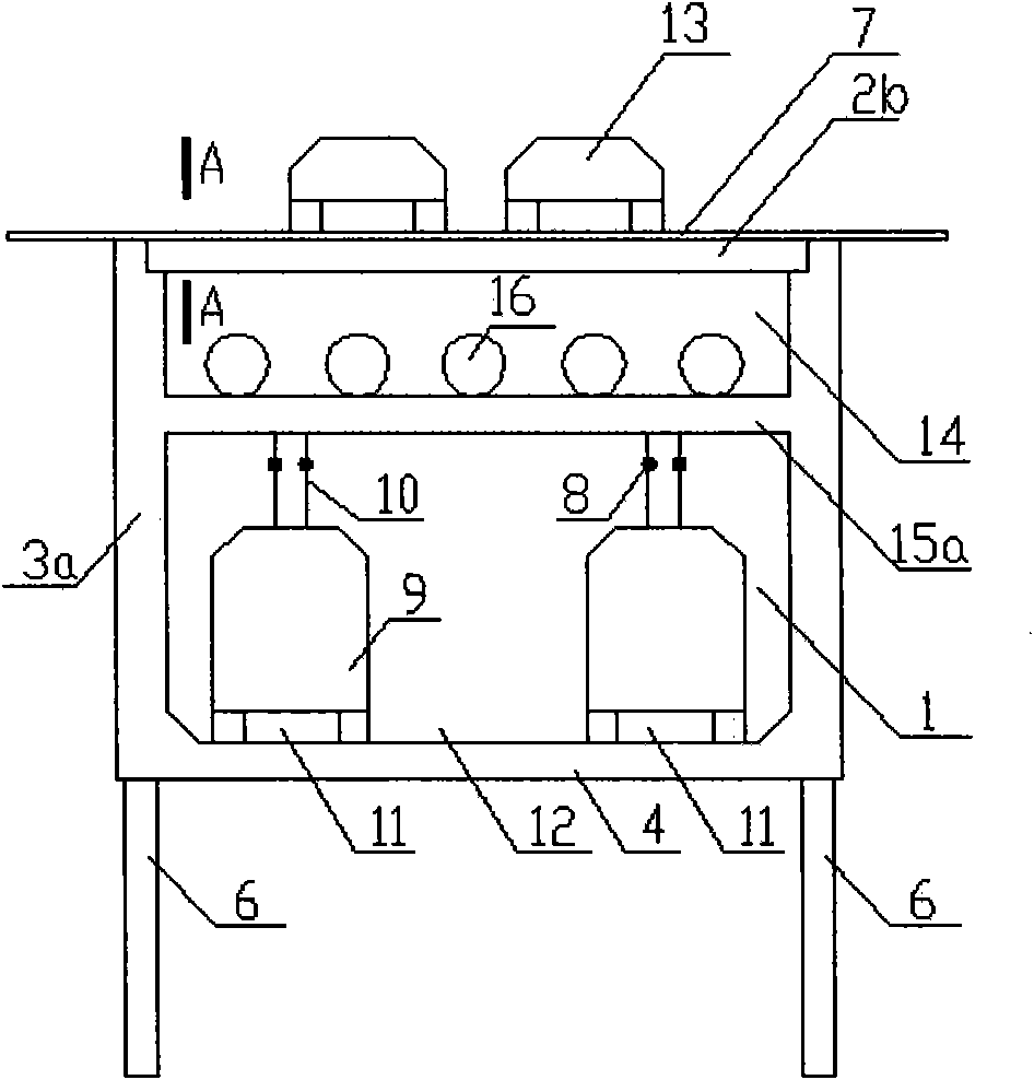
[0052] see figure 2 , The underground comprehensive passage adopts a combined structure of box culvert and prestressed hollow panel 2b, which is composed of prestressed hollow panel 2b, side wall 3a, middle plate and support 15a and bottom plate 4. The prestressed hollow panel 2b adopts a horizontal arrangement, that is, the longitudinal direction of the cavity 17 of the prestressed hollow panel 2b is perpendicular to the longitudinal direction of the underground comprehensive passage. The side wall 3a, the middle plate and support 15a, and the bottom plate 4 adopt a reinforced concrete structure or a prestressed reinforced concrete structure, and the prestressed hollow panel adopts a pretensioned prestressed reinforced concrete structure or a posttensioned prestressed reinforced concrete structure. All the other are the same as embodiment one.

Embodiment 3

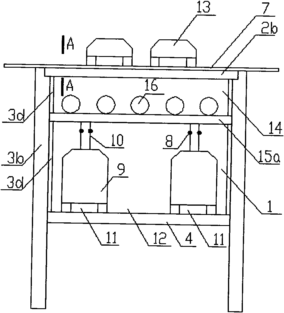
[0054] see image 3 , using the shallow underground space of the ground road 7, combined with the ground road 7 to set up an underground comprehensive passage. Porous (not shown on the figure), the underground comprehensive passage lower layer 1 is used as the passage of the trolley bus 9, the underground comprehensive passage upper layer 14 is used as the passage of the pipeline 16, and the surface layer is laid on the top of the prestressed hollow panel 2b as the ground road 7, and the underground comprehensive passage The side wall 3b or the roof 2b of the upper floor 14 is provided with a special installation and inspection port (not shown on the figure), and the bottom of the middle plate and support 15a is provided with an overhead catenary 8, which is connected to the trolleybus 9 by contact with the trolleybus current collector 10. For power supply, the ventilation facility (not shown on the figure) that only needs to satisfy the breathing needs of the drivers and pass...


PUM


Abstract

The invention belongs to the field of municipal and traffic engineering and relates to a ground-road comprehensive tunnel for underground pipelines and trolley buses. The technical scheme is that the underground compressive tunnel is set by combining with the ground roads, wherein the underground compressive tunnel has a rectangular cross section, and is vertically divided into two layers and is transversely provided with one single pore or multiple pores, the lower layer is used as a trolley bus comprehensive tunnel, the upper layer is used as a pipeline tunnel, the top plates are used as the ground roads, and the lower layer is only provided with ventilating facilities by which drivers and conductors can breathe. The technical effects include: the traffic of the underground trolley buses becomes a brand new public transport mode in which the special roads are set, and the traffic speed and ability are greatly improved; the oxygen is not consumed, no waste gas discharges, and the ventilating facilities only need to meet the breathing requirements of the drivers and conductors, so that the operating cost of ventilation is saved; the ground traffic space is saved; and the ground roads, the underground tunnels of the trolley buses and the pipeline tunnels are organically combined. The comprehensive tunnel is suitably used for developing underground trolley bus transportation in cities, and can also solve the problems of laying and maintaining the pipelines at the same time.

Description

Technical field: [0001] The invention belongs to the field of municipal and traffic engineering, in particular to an integrated channel for underground pipelines and trolleybuses combined with ground roads. Background technique: [0002] The prior art of trolleybus: since the birth of trolleybus at the beginning of the 20th century, the application history has been nearly one hundred years. Trolleybuses are directly driven by electricity, have no internal combustion engine, do not emit exhaust gas, have low noise and low pollution. Since their birth, they have been widely used in ground transportation in cities in various countries because of their many advantages, occupying an important position, but there are also the following insufficient: [0003] 1. Since the trolleybus is connected to the fixed overhead catenary and the rod-shaped current collector of the vehicle (commonly known as a braid, also known as a collector, which is composed of a collector rod and a collect...

Claims


Application Information

Patent Timeline
Patent Type & Authority Applications(China)
IPC IPC(8): E01C1/00B60M1/12E02D29/045
Inventor 马兴华
Owner 马兴华
Why Eureka
Try Eureka