Permanent magnet generator rotor
A technology for permanent magnet generators and rotors, applied to magnetic circuit rotating parts, manufacturing stator/rotor body, magnetic circuit shape/style/structure, etc., can solve the problem of reducing generator output, increasing reluctance, and reducing the effectiveness of permanent magnets Magnetic flux and other issues, achieve the effect of reducing weight and moment of inertia, convenient installation and disassembly, and reducing the amount of magnets
- Summary
- Abstract
- Description
- Claims
- Application Information
AI Technical Summary
Problems solved by technology
Method used
Image
Examples
Embodiment 1
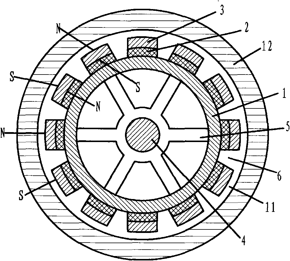
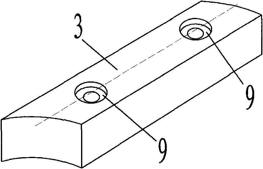
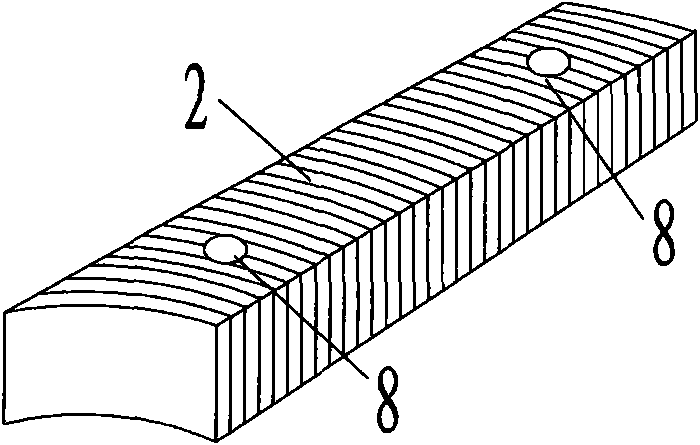
[0026] figure 1 This is a cross-sectional view of the structure of Example 1. The tile-shaped permanent magnet 3 and the yoke base 2 made of silicon steel sheets are fixed with stainless steel bolts 16 on the cylindrical yoke 1 made of silicon steel sheets (see Figure 7 ). The magnet 3 has a countersunk hole 9 (see figure 2 ), so that the mounting bolt head sinks into the magnet. There are through holes 8 on the yoke table (see image 3 ) To allow the bolt 16 to pass through. The yoke 1 is mounted on the spokes 5 with the shaft 4 to form the overall rotor. The function of the yoke table is to reduce the self-short circuit of the magnetic field lines, so that more magnetic field lines enter the stator and participate in power generation. In the present invention, the magnetic lines of force start from the N pole of the first magnet, pass through the air gap 11, the stator 12, and then through the air gap 11, enter the S pole of the adjacent permanent magnet, and pass throu...
Embodiment 2
[0028] Stamping silicon steel sheet into Figure 5 shape. After stacking, use axial bolts (not shown) to pierce firmly, so that the yoke base and the cylindrical yoke become one body, which is called the toothed yoke 7. The rest of Embodiment 2 is the same as Embodiment 1.
Embodiment 3
[0030] In the yoke made of laminated silicon steel sheets in Example 1, a 3-15 mm thick ring-shaped iron plate 10 with the same shape as the silicon steel sheet is sandwiched. The position of the iron plate is such that the yoke base is installed The hole 8 coincides with the mounting hole 15 on the iron plate. This is to avoid the difficulty of drilling holes parallel to the surface in the silicon steel sheet stack.
PUM
 Abstract
Description
Claims
Application Information
 - R&D
- Intellectual Property
- Life Sciences
- Materials
- Tech Scout
- Unparalleled Data Quality
- Higher Quality Content
- 60% Fewer Hallucinations
Browse by: Latest US Patents, China's latest patents, Technical Efficacy Thesaurus, Application Domain, Technology Topic, Popular Technical Reports.
© 2025 PatSnap. All rights reserved.Legal|Privacy policy|Modern Slavery Act Transparency Statement|Sitemap|About US| Contact US: help@patsnap.com


